C53000-X5399-C001-5, 02.2023
SIPROTEC 5 Compact Product Information
Spannungsklemmen, Einbauort D, wenn vorhanden
Anschlussarten gemäß UL:
• Leitungsquerschnitt: AWG 20 bis 14. Abisolierlänge: Je nach
Aderendhülsentyp: 12 mm bis 15 mm.
Anschlussarten gemäß IEC:
• Leitungsquerschnitt: 0,5 mm² bis 2,5 mm². Abisolierlänge: Je nach
Aderendhülsentyp: 12 mm bis 15 mm.
Zulässiges Anzugsdrehmoment an der Klemmschraube: max. 0,5 Nm.
Zulässiges Anzugsdrehmoment an der Flanschschraube: max. 0,25 Nm.
EN – Product Information
Use as Prescribed
SIPROTEC 5 Compact is a protection and control device for the protection,
automation, and monitoring of electrical power-supply systems.
Hazardous voltages can result in death, physical injury. or
substantial material damage. Laser radiation results in eye injuries.
Static discharging destroys the device. Observe the safety
instructions in the manuals! Comply with technical data!
Only a qualified electrician may connect, ground, label,
commission, and isolate the equipment (devices and modules).
Only instructed persons may replace batteries and maintain the
circuits on which batteries are involved.
Observe the manuals. The system is intended exclusively for use
in accordance with the manuals. The manuals contain installation
instructions, connection notes, terminal diagrams, connection
diagrams, and technical data.
Manuals:
https://support.industry.siemens.com/cs/start?lc=en
-WW
https://www.ea-testreports.siemens.com
Storing and Usage Conditions
► Check the packing for external transport damage. Keep and use the
packing for storing and transport.
► Storing: -25 °C to +55 °C (-13 °F to +131 °F), for max. 16 h -40 °C to
+85 °C (-40 °F to +185 °F). Clean environment. Dry room, so that
condensate and ice is prevented from forming.
• Operating temperature -10 °C to +55 °C (+14 °F to +131 °F), for max.
96 h -25 °C to +70 °C (-13 °F to +158 °F), for max. 16 h -25 °C to +70 °C
(-13 °F to +158 °F) (refer to the manuals)
• Max. altitude 2000 m (6561.68 ft) above sea level
• Degree of protection:
Panel surface mounting: IP20;
Panel flush mounting: front: IP51 (with the supplied seal), connection
area (rear side): IP20;
For operator protection: IP2x for current terminal, IP2x for voltage
terminal
• Degree of pollution 2 acc. to IEC 60255-27
• Safety class I
CAUTION! Use Only Allowed Batteries
Wrong batteries lead to a risk of fire, chemical burn, and explosion.
► DO NOT recharge, disassemble, heat above +100 °C (+212 °F), or
incinerate batteries.
► Keep away from children.
► Exchange batteries only with VARTA or Panasonic CR2032 or BR2032.
► Dispose the used battery promptly. Comply with laws.
Device Disposal: Your Legal Obligations
► Remove batteries.
► Dispose the electrical product at a garbage pick-up.
DO NOT mix with normal household waste.
Vendors must take back the electrical product free of charge.
Max. Rated Data of the Output Contacts in Accordance with
UL Certification
Field wires of control circuits shall be separated from other circuits with
respect to the end use requirements.
Type 1 if mounted into a door or front cover of an enclosure.
Requirements for all Connection Lines
Use copper conductors only, at least certified for a temperature of +105 °C
(+221 °F).
Grounding Terminal
Before any connections are made:
► Ground the equipment at the grounding terminal.
► Connect base and expansion modules with all expansion modules.
• Conductor cross-section: at least 4 mm²
• Tightening torque for the M4 grounding screw: 1.2 Nm to 1.6 Nm
Current Terminals (Panel Flush Mounting)
Max. 2 connections per pole.
Connection types according to UL:
• Connection with prepared solid conductors. Conductor cross-section
14 to 12 AWG. Stripping length 15 mm (0.59 in).
• Connection with UL-listed ring-type lug, for example, PIDG by Tyco.
Stranded wires with conductor cross-section 12 to 10 AWG.
Connection types according to IEC:
• Connection with prepared solid conductors. Conductor cross-section
2.0 mm² to 4.0 mm². Stripping length 15 mm (0.59 in).
• Connection with stranded wires with ferrules or pin cable lug.
Conductor cross-section 2.0 mm² to 4.0 mm². Contact length 15 mm
(0.59 in).
• Connection with ring-type lug, for example, PIDG by Tyco. Stranded
wires with conductor cross-section 2.6 mm² to 5.2 mm².
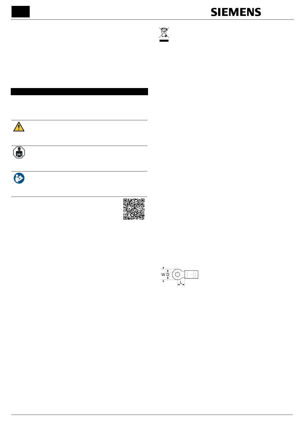
Measurements for appropriate ring-type lugs:
D (for bolt): 4.3 mm to 5.2 mm (0.17 in to
0.2 in)
W: 6.4 mm to 9.5 mm (0.25 in to 0.37 in)
L: 7.1 mm to 7.7 mm (0.28 in to 0.3 in)
Permissible tightening torque at the terminal screw: 2,7 Nm. For conductor
cross-section 2 mm² (0.003 in²): 2.0 Nm. Maximum allowed speed of the
used tool: 640 RPM.
Voltage Terminals, Slot A, B
Connection types according to UL:
• Connection with prepared solid conductors or stranded wires.
Conductor cross-section 20 to 14 AWG. Stripping length 12 mm
(0.47 in).
Connection types according to IEC:
• Connection with prepared solid conductors or stranded wires.
Conductor cross-section 0.5 mm² to 2.5 mm². Stripping length 12 mm
(0.47 in).
• Connection with stranded wires with ferrules. Conductor cross-section
0.5 mm² to 2.5 mm². Contact length 12 mm (0.47 in).
For currents from 5 A to 10 A use conductor cross-section 14 AWG (UL)/
2.5 mm² (IEC).
Permissible tightening torque at the terminal screw 1.0 Nm. Maximum
allowed speed of the used tool: 640 RPM.
 Loading...


