Commissioning
6.3 Adjustment and initial commissioning
SIWAREX WL200
Operating Instructions, 07/2016, A5E02199611B-03
35
General procedure for corner load adjustment
The load cells are passive sensors: You should therefore follow the instructions in the
manual for the weighing module primarily. When they are installed in hazardous areas, the
instructions for the Ex i interface or for the Ex barrier must also be followed.
When the corner load for a scale has to be checked, impermissibly large deviations in the
weight indication can occur in the case of load cells that are not current-calibrated.
The corner load errors can be electrically compensated. This is done by matching the
individual measured values to the smallest measured value by connecting additional
resistors. For details of how to do this see section Example for corner load adjustment
(Page 35)
The resistors are connected in series with the load cell measuring signal. The appropriate
resistor will reduce the measuring voltage until it is equal to the smallest voltage. The
temperature coefficient must be suitably small, due to connection of the resistors in the
measuring circuit: 0.25 ppm/K to 10 ppm/K.
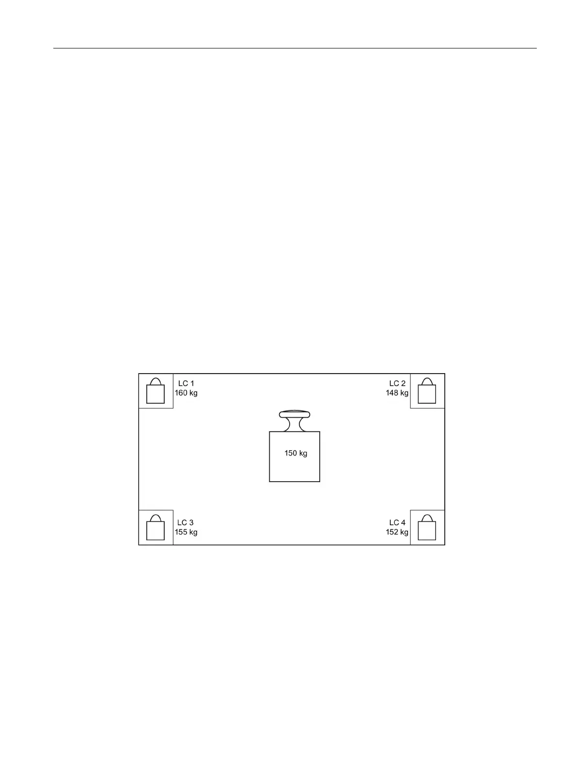
Example for corner load adjustment
Example data for corner load adjustment
The corner load adjustment described below as an example is based on the following data:
Scale
Platform scale with 4 load cells
Rated load
500 kg
Rated
character-
istic value
2.0 mV/V
Figure 6-2 Test process / scale

 Loading...