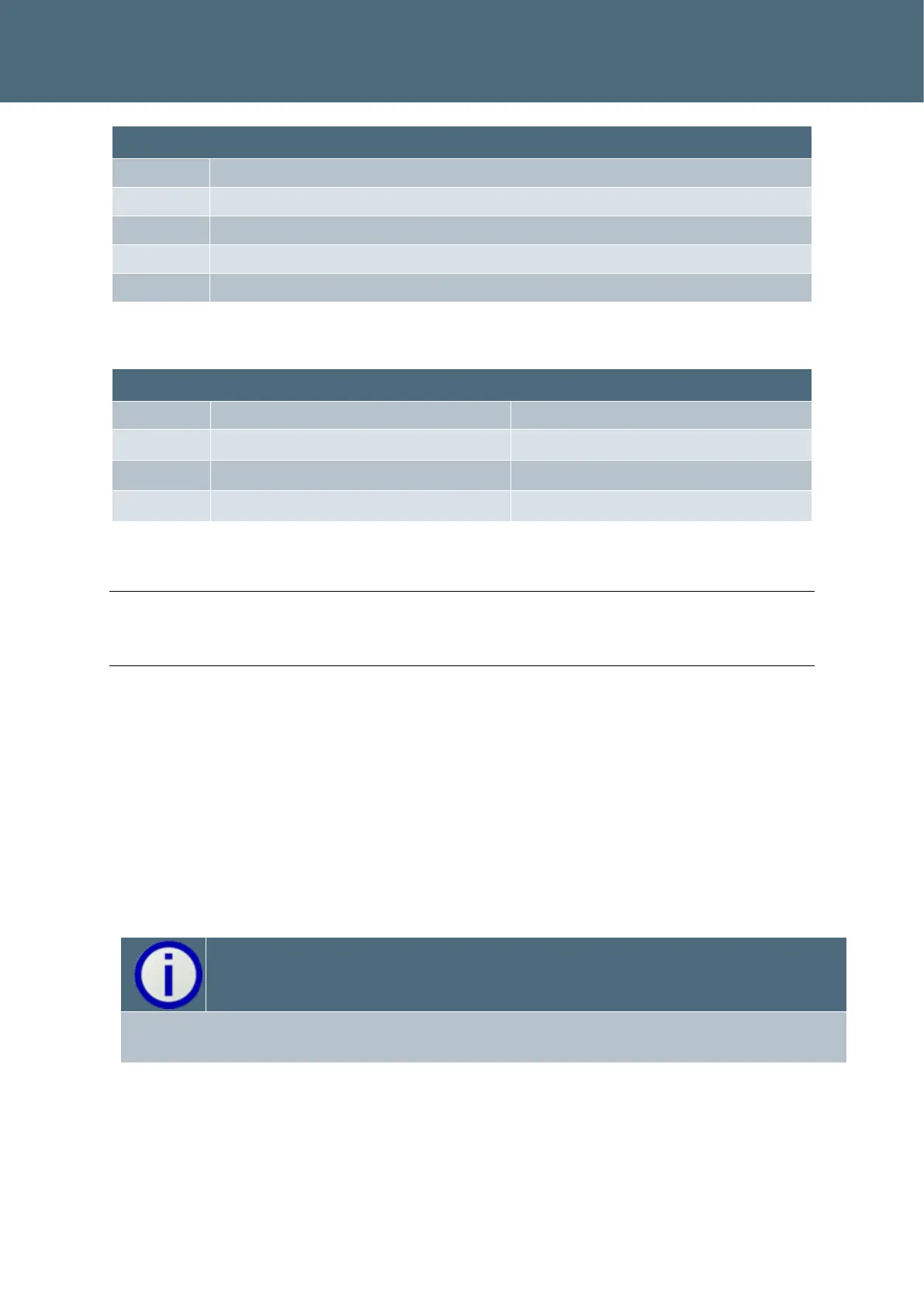
Table 4 : Inductance Jumper Settings for Detection
Note
In practice inductance ranges overlap so it is possible to use a lower range in some circum-
stances. This may give better performance, particularly for bicycle detection.
2.2. SLD4 Sensitivity
The detector threshold may either be set in “Hz” or as a percentage of loop inductance
change (%ΔL/L ). Which you use only depends upon which is most convenient for the applica-
tion. In general, it is recommended that “Hz” mode is used for large vehicles (tram, bus), as
this provides easier value adjustment for large vehicles. The value is a whole number in the
thousands range, for an inductance change it would be a two decimal place number.
The “Hz” setting is slightly dependent upon frequency, so if you change the loop frequency
then the sensitivity in “Hz” may need to be changed higher or lower in proportion to the loop
frequency change. This is the disadvantage of using the “Hz” setting mode.
The standard SLD4 detector supports only “Bicycle” mode whereas the remaining modes re-
quires an enhanced SLD4 detector.