A limitation of the detector is that only two sets of class definitions can be made, these are
applied to loop1 and 2, and loop 3 and 4. In single loop mode it is only possible to define two
classification definitions.
When configured for single loop classification the class definitions for lane 1 apply to loop1
and loop2, and lane 2 to loop3 and loop4.
The available classification options allow the vehicle speed and length to be used as criteria
for defining a vehicle class. A vehicle meeting a class definition causes an internal class de-
tect event which may be assigned to physical output as required. The class detect and vehicle
detect events can be individually assigned to the physical outputs and GSPI.
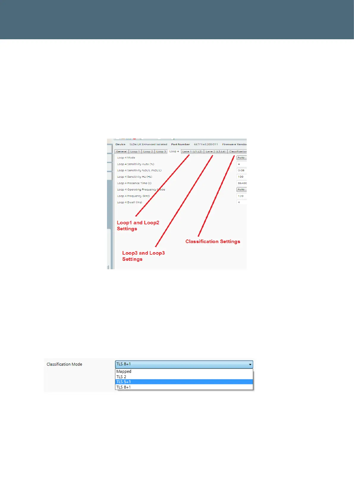
Figure 16 : Location of Classification Settings
7.3.1. Mapped Classification
The mapped classification (classification bins) config tab, as shown in Figure 18 allows up to 9
classification bins (also referred to as class) to be mapped. The ‘Mapped’ setting shown Figure
17 must be selected to use this feature. Each bin has a Class ID which can be used to customise
the classification value reported in the vehicle data.
Figure 17 : Classification Mode Selection (General Tab)
The classification bins can be configured in terms of min/max length and speed, and vehicle
profile class (TLS vehicle classes), or a combination of both. The bins can be mapped to the
digital outputs, as shown in, it is possible to map several classification bins to a single output
if required. It is also possible to configure classification bins which overlap, if a vehicle meets