7.3.1.2. Classification Example 2 – Mapping Speeding vehicles to digital outputs
Requirement – Detection on digital output 1 for small vehicle speed >70mph on lane 1, de-
tection on digital output 2 for Truck or Bus speed >60mph on lane 1
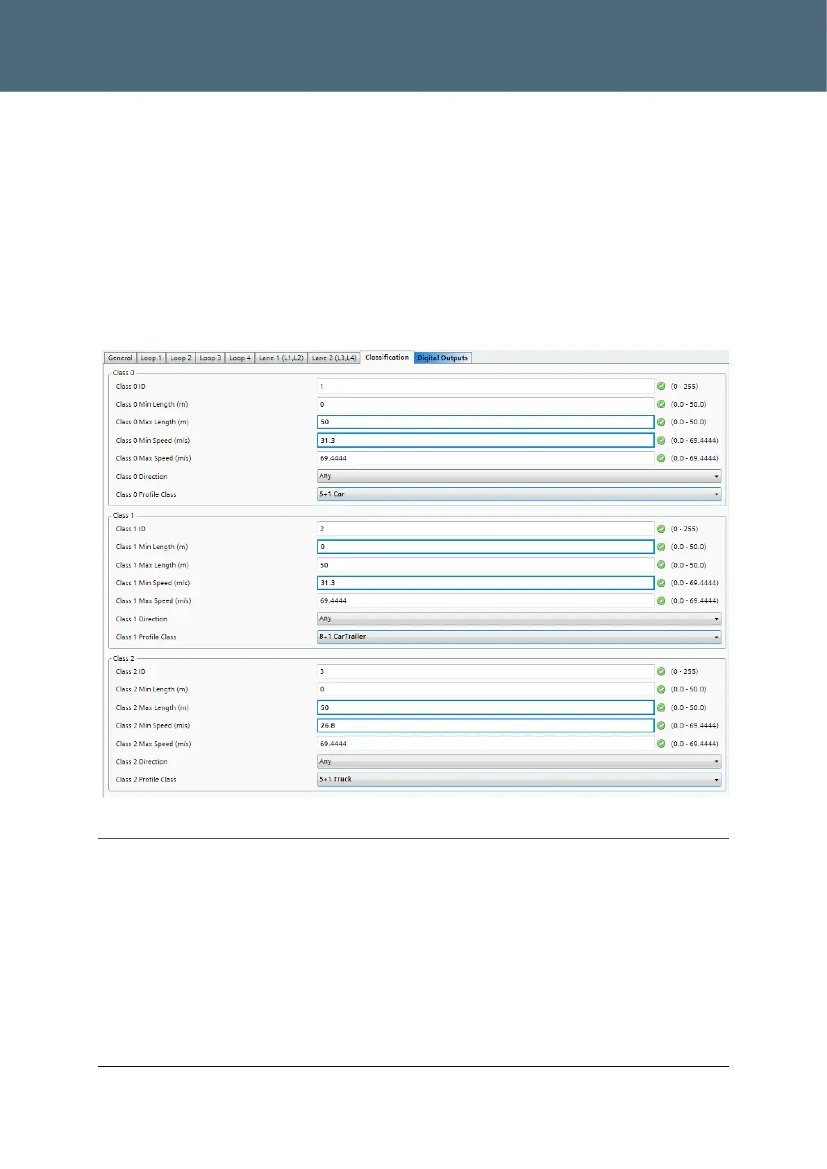
As shown in Classification bins (Class 0,1 and 2) filter on the selected profile class and vehicle
speed, length min/max set to the extremes to ensure the vehicle length will not affect the
classification.
60mph = 26.8m/s, 70mph = 31.3m/s
Class 0 set to profile class 5+1 Car, to include motorbike and van.
Class 3 (not shown in figure below) set to profile class 5+1 TruckTrailerArticulated, min speed
26.8m/s
Figure 21 : Example 2 Classification bin configuration
Note
If the classification bins overlap, change the ‘Class ID’ to a discrete binary bit integer values to
ensure the overlapped classification value makes sense. An example of what this means is;
with the following config, a Car with 4.6m length will be given classification value of 3 (binary
0011), and a Car with length 4.9m will be given classification value of 6 (binary 0110);
Class 0, ID=1 (binary 0001), min len=0m, max len =4.8m, Profile class=5+1 Car
Class 1, ID=2 (binary 0010), min len=4.5m, max len =5m, Profile class=5+1 Car
Class 2, ID=4 (binary 0100), min len=4.8m, max len =5.5m, Profile class=5+1 Car
These alternative mapped classification values are included in the GSPI serial interface/mes-
sages, but not the SiTOS interface (reference SLD Handbook for information).