Structure and function
11
Building Technologies
A6V10099835_a_en
Fire Safety & Security Products 12.2007
4 Structure and function
This chapter describes the structure and function of the extinguishing control unit. It
provides an overview of what options are offered by the extinguishing control unit.
A more detailed description of the individual procedures is provided in the
"Operation" and "Maintenance" chapters.
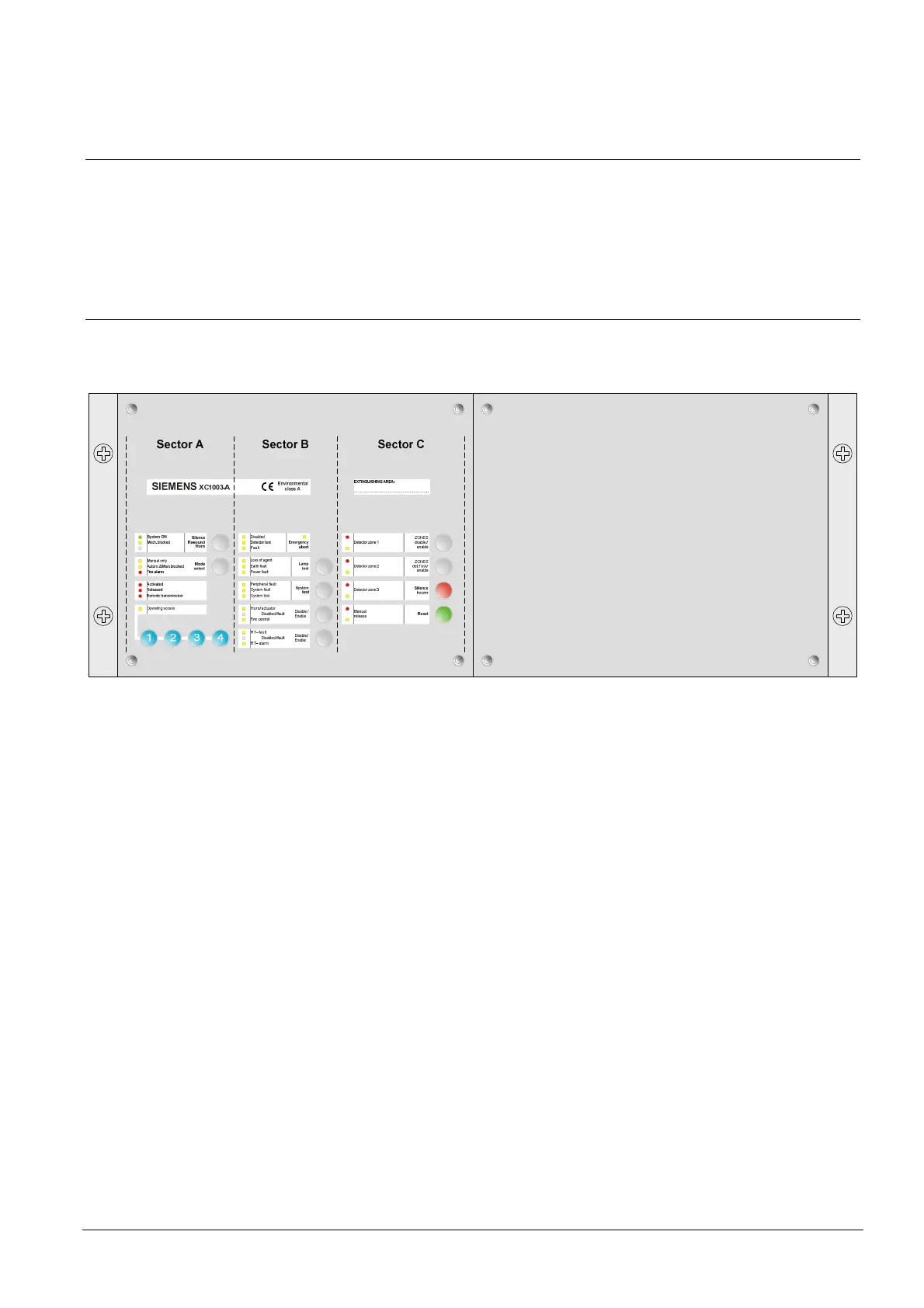
4.1 Indicators and operating elements
The figure below represents the indicators and the operating elements of the
extinguishing control unit.
Fig. 2 Indicators and operating elements
The operating interface consists of the following elements:
Light emitting diodes (LEDs):
The red LEDs signify states "Fire alarm" (alarm detectors), "Activated"
(activation of extinguishing initiated), or "Released" (extinguishing activated).
The yellow LEDs signify system parts "Disabled" or in "Test mode" or "Fault".
Keys:
The keys are used for operating the extinguishing control unit and for entering
the access code to allow system operating (Access level 2 enabled).
 Loading...


