SDM3045X Service Manual 21
Check the Power Supply
There are two power connectors through which the analog board and main
board can be supplied electricity. For the analog board, there are three voltage
test points on its power connector. For the main board, there is one test point.
Before performing the power supply testing procedure, please make sure that
the multimeter is grounded correctly through the protective lead of the power
cord. Take care not to touch or even disassemble the power supply module
without any safety precautions, or you may probably suffer from electric shock
or burn. Here are procedures for testing the power supply:
1. Disconnect the power cord of the multimeter and then check whether the
fuse has been burnt out.
2. Remove metal shell of the multimeter using a driver, and then disconnect
the power connector connected to the main board.
3. Focus on the Power Connector for the analog board, which contains five
pins from Pin 1 to Pin 5. You can test the adjacent pins that are marked with
Blue, Brown, Yellow and White to check whether the AC voltage value is
within the corresponding specified range using a digital multimeter. The
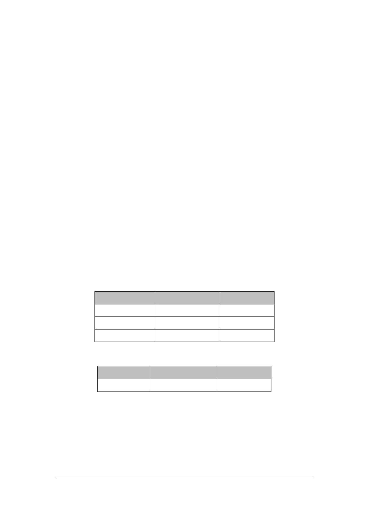
voltage parameters to be tested are listed in table below:
Table 6-2 Test AC voltages for the analog board power connector
If each tested voltage value is within the corresponding spec range referring to
the table above, then the power supply works normally. Otherwise, it proves to
be faulted, please return it to the factory to have it repaired or contact
SIGLENT.
Note: The main power supply provides an input fuse to protect against the
danger of fire in the event of a failure of the power supply circuitry. However,