SIGLENT
SDM3045X Service Manual 23
Analog board Clock Check
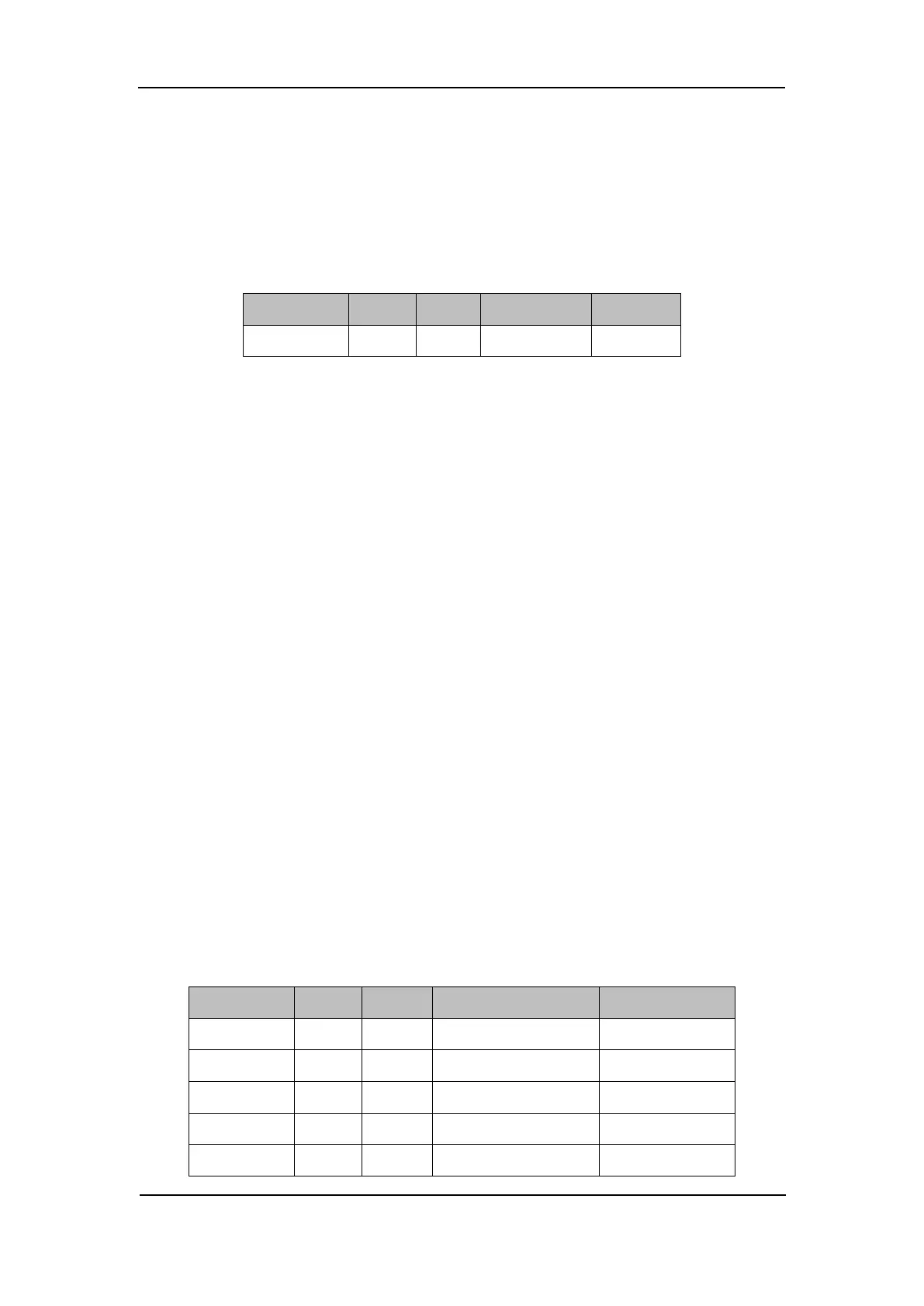
Analog board clock is the internal system clock of the multimeter. To verify if
the clock on the analog board works normally, please test the clock frequency
listed below using an oscilloscope.
Table 6-5 Clock Source of the analog Board
Check the Main Board
If the main board does need to be removed from the metal shelf located inside
the multimeter, place it on a clean, insulated mat. Testing procedures for the
main board are as follows:
1. Several types of connectors are located on the main board. Check if all
these are connected properly.
2. Make sure that the connectors on the main board are properly connected,
then connect the multimeter to AC power and turn it on. Check if the voltage
values at all test points are within the spec range using a digital multimeter.
The voltage parameters to be tested are listed in table 5-6:
Voltage Check
Test the voltage points on the main board in the table below. To locate the test
points, please refer to the drawing of the main board. If not each tested voltage
value is within the corresponding spec range referring to table 5-6, it proves to
be faulted, please return it to the factory to have it repaired or contact
SIGLENT.
Table 6-6 Test DC voltages of the main board