this fuse will not fail ("open" or "blow") in normal power supply operation except
after a significant overload occurs. Replace the entire main power supply
assembly if the input fuse fails.
Check the Analog Board
If it is desired to remove the analog board from the metal shelf inside the
multimeter, you’d better place it on a clean, insulated mat. Here are procedures
for testing the analog board:
1. Several types of connectors are used on the analog board. Check to make
certain that all of these are connected properly.
2. After checking these connectors, then connect the multimeter to AC power
and power it on. Check if the voltage values at all test points are within the
specified range using a digital multimeter. The voltage parameters to be
tested are listed in table 5-3:
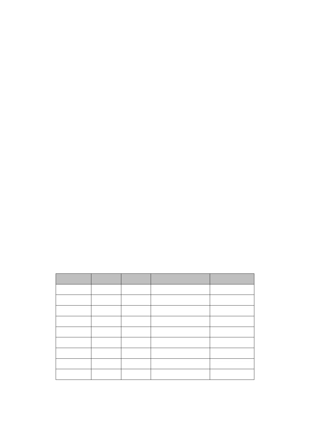
Voltage Check
Test the voltage points on the analog board in the table below. To locate the
test points, please refer to the drawing of the analog board. If not each tested
voltage value is within the corresponding spec range referring to table 5-4, it
proves to be faulted, please return it to the factory to have it repaired or contact
SIGLENT.
Table 6-4 Test DC voltages of the analog board