SA300 Installation Instructions
4.3. Installation Examples
•
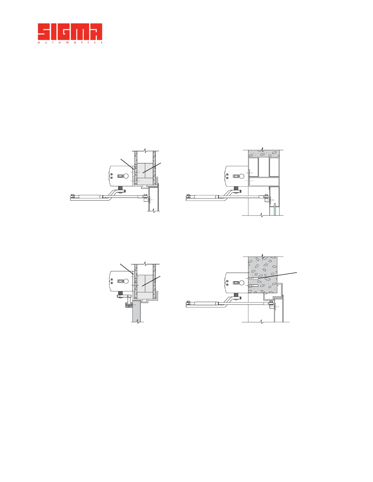
Ensure there is solid structural support in the mounting surface (wall) behind the header unit for the
appropriate mounting hardware to be secured to.
•
A spacer or filler plate made of solid material may be required to compensate for any gap between the
door frame/header unit and mounting surface.
•
Before mounting the header unit, ensure that access holes for the power supply cables are aligned and
properly prepared.
•
Shown below are examples ONLY. Use your discretion, follow all local building and security codes.
•
On composite or hollow wood doors we recommend the use of thru-bolts when securing the arm shoe
or slider.
Masonry
expansion bolts
•
Standard push arm can accommodate reveals up to 12in (30.5 cm)
•
Standard pull arm can accommodate reveals up to 6in (15 cm)
Other arms are available for deeper reveals – please contact your local reseller for details.
Concrete / Masonry
(PUSH)


 To Next Page