SA300 Installation Instructions
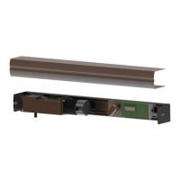
18” for 90◦
FOR PUSH APPLICATION
1/2" hole to lock gearbox
Figure 4-8 Push Arm Positioning
4.5.2. PUSH Arm Installation
•
Attach or re-adjust the push arm to be approximately 45° from parallel to the door frame as shown in
Figure 4-8. Lock position using 3/16 socket screw included.
•
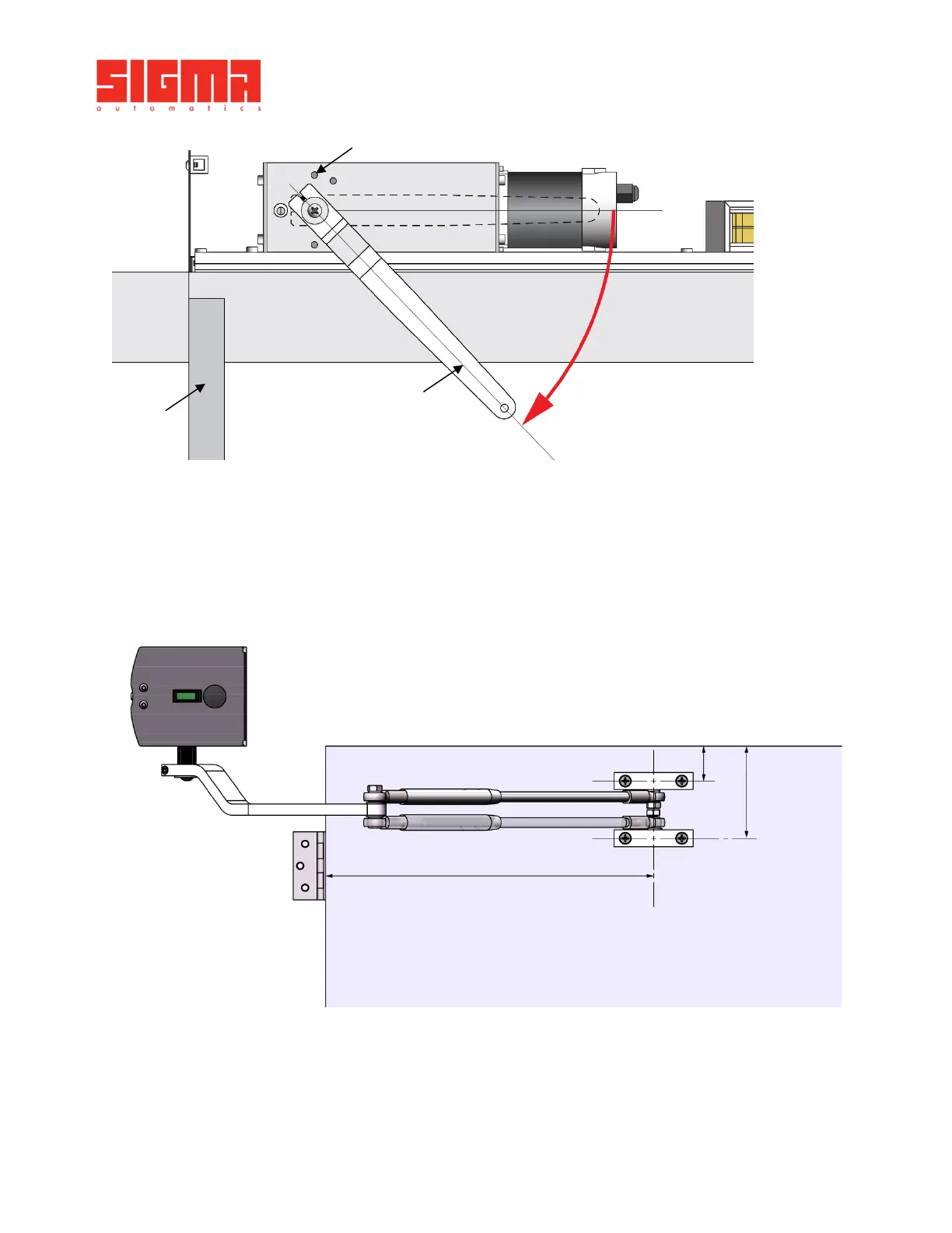
With the door still held in position, attach the forearm and block to the door 14-1/2" from the hinge side
door edge, in the high or low mount position as shown in Figure 4-9. Use your discretion: The forearm
must be level with the operator arm, adjust accordingly.
Figure 4-9 Push Arm Installation
•
Fix the arm to the operator spindle using supplied PH3 screw.
•
Push the door slightly to release the metal rod or screwdriver from the gearbox. If the gearbox was pre-
loaded using the motor, remove the jumper wire between COM and ACT2 on the control board.
•
With the rod removed, the door should close as if it had a manual door closer installed.
•
The door operator is now ready for programming.