24 von 37
V 07.17
Service Manual BXT3-13/16/19ENGLISH
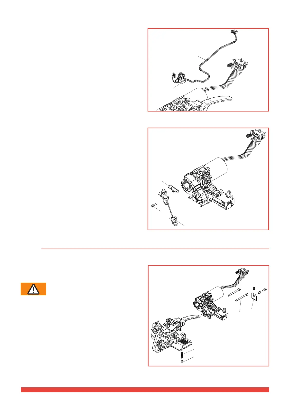
5.3.2 Replacing the rocker lever wiring harness
Dismantling
► Remove the form wiring harness (Chapter 5.3.1)
► Disconnect the 5-pin connector of the wiring harness
# 103 from the control board and support # 79.
► Remove the wiring harness # 103.
Fitting
► Carry out the assembly in reverse order.
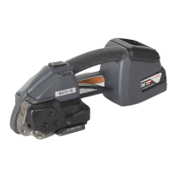
5.3.3 Replacing the welding mechanism wiring harness
Dismantling
► Remove the welding mechanism from the base plate
(Chapter 5.4.1).
► By removing cylinder screw # 104, loosen the assem-
bly bracket # 195.
► Now the connector can be removed from the assembly
bracket by unlocking the barbed hook.
► Remove connector from wiring harness # 106 from
control board.
Fitting
► Carry out assembly in the reverse order. Observe the
correct position of the wiring! (Chapter 5.11).
► Tighten cylinder screw # 104 with a torque of
0.6 Nm.
►
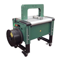
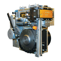
5.4 Mechanical components
5.4.1 Disassembly of the welding mechanism
Dismantling
► Remove both housing parts (chapter 5.2).
WARNING
Risk of injury! Remove the knife # 166
(chapter 4.1.3) .
► Remove the threaded pin # 86 with spring # 169.
► Remove two centring screws # 101.
► Hold the welding unit on the motor and remove to the
rear. In doing so, lift lever.
Fitting
► Carry out assembly in the reverse order.
► Tighten centring screws # 101 with a torque of
6.0 Nm.
► Screw the threaded pin # 86 until it ushes with the
base plate.
103
79
195
104
106
86
169
101
166