AG25
Installation English
AG25 · Date 19.07.2022 · Art. No. 87450 · Mod. status 157/22
30
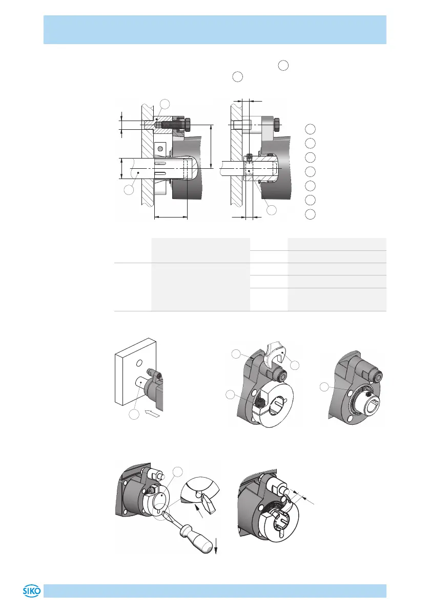
4. Tighten the screw for the torque support
1
by applying 2Nm. Lock
using a size 10 open wrench
5
.
1
Torque support
2
Shaft
3
Shaft groove
4
Clamp ring screw
5
Open wrench
6
Grub screw
7
Screwdriver
Fig. 1: Mounting dimensions
Tab. 1: Mounting dimensions
dim. øD ø10
H9
(Torque pin B)
ø6
H9
(Torque pin A)
dim. L1 30 ±0,5
dim. L2 20 ... 25
dim. ød
suggestion
ø14h9 (clamp ring)
ø10 f8 (feather key groove)
ø12 f8 (clamp ring, shaft
for feather key)
dim. L3 4.9
dim. L4 5 (width groove)
dim. L5 8 (feather key
DIN 6885/1-A-4x4x8mm
Fig. 2: Mounting
Fig. 3: Fastening
torque for screws
Fig. 4: Shaft with
feather key groove
7
Fig. 5: Transport lock
L
Fig. 6: Clamp ring, shaft
with feather key groove
 Loading...

