AG25
Installation English
AG25 · Date 19.07.2022 · Art. No. 87450 · Mod. status 157/22
29
4.1 Mechanical mounting
Loss of type of protection
Loss of the type of protection caused by worn sealing rings in the ball
bearing and radial shaft seals.
` Operate the actuator within the admissible parameters
(see chapter 9).
Destruction of main bearings
Improper installation (e. g. tension on the driving shaft) causes addi-
tional heat development and destruction of the actuator in the long term.
` Ensure a low shaft and angle oset between shaft and accommodation
bore by applying appropriate manufacturing methods
(see Fig. 1 + Tab. 1).
Actuator failure
` When mounting pay attention to the IP type of protection (see chapter 9).
` Do not open the actuator yourself (exception: see chapter 6).
` Avoid impact on the device.
` Do not modify the device in any way.
Destruction of casing
If torque pin (see Fig. 3) is mounted improperly, this will lead to a
destruction of the casing.
` Please observe max. admissable starting torque of 2Nm.
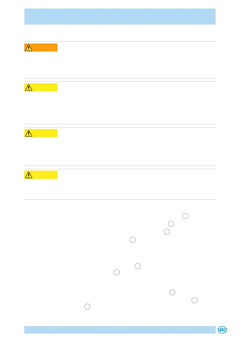
Preparing mounting (Fig. 1, Fig. 2, Fig. 3, Fig. 5, Fig. 6):
1. Make bore (øD) with distance (L1) to the driving shaft
2
.
2. Observe length (L2) and diameter (ød) of shaft
2
.
3. Untighten the M5 screw in the toque support
1
.
4. Lever out the transport lock
7
with a screwdriver. Insert screwdriver
into the clamping ring recess.
Mounting (Fig. 1, Fig. 2, Fig. 3, Fig. 4, Fig. 6):
1. Slide the actuator on the shaft
2
until the torque support has
reached the stopper
1
. To avoid fretting corrosion, grease torque pin
A in ø6 area. You may slightly adjust the torque support to the instal-
lation conditions via a long hole).
2. In case of clamp ring version, tighten the screw
4
with 3Nm.
3. In case of shaft with feather key groove, provide an groove
3
on grub
screw
6
in the customer's shaft to ensure the dismantling of the
actuator.
CAUTION
 Loading...

