AG25
Commissioning English
AG25 · Date 19.07.2022 · Art. No. 87450 · Mod. status 157/22
36
5 Commissioning
Latch-up eects
Output stage of the driver is damaged.
` The operating voltage of the device must be switched on together with
the downstream electronics unit (e. g. control).
Please carefully read the information on the actuator's mechanical and
electrical connection. This will ensure a trouble free commissioning and
operation.
Before operation, please check again:
• that the supply voltage's polarity is correct.
• correct connection of cable and signal lines.
• secure actuator fixation on the hollow shaft.
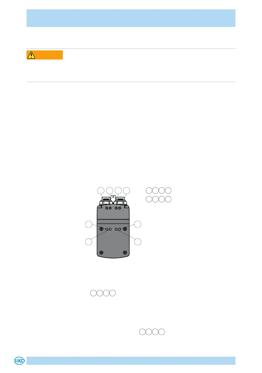
LED and control keys
The actuator has various LEDs, which indicate the statuses of drive and
Ethernet module. The operating elements are located underneath the
cover (Fig. 13, Fig. 14).
1 2 3 4
Ethernet modul status LEDs
5 6 7 8
Drive status LEDs
1
2
3
4
5
6 7
8
Fig. 12: Status Display
Ethernet modul status
The LEDs
1 2 3 4
inform about the status of the Ethernet module. The
functions of the Ethernet module status LEDs are permanently defined and
cannot be changed. For a description of the functions of the module status
LEDs refer to the relevant user manual.
Drive status
With factory settings, the LEDs
5 6 7 8
(Fig. 12) inform about the
drive's status. You can configure the functions of the drive status LEDs.
 Loading...

