AG25
Installation English
AG25 · Date 19.07.2022 · Art. No. 87450 · Mod. status 157/22
35
Ground connection (PE)
To protect the unit against interference, the shields of the signal lines and
power cables must be connected on both sides. Potential dierences result
in inadmissible currents on the shield. Put the PE connection
4
between
the plug connectors on the ground wire potential (Fig. 7). Use 6.3 mm flat
connectors with a short strand 2.5… 4mm² (not supplied). Fore multiple
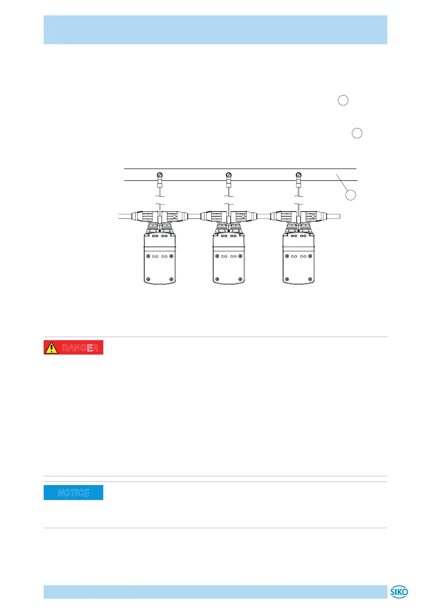
actuators we recommend that you connect grounding to a PE rail
1
(Fig. 11).
Fig. 11: Ground bar
1
Admissible power input
Torque overloading
In case of massive, shock-type overloading, the actuator can be irrevers-
ibly damaged mechanically (e. g., block travel). When the actuator is over-
loaded, the motor current will be limited to the set value (for the proce-
dure of setting the current limit please refer to the user manual). Permanent
overload results in deactivation of the actuator (e. g., contouring error).
` Adhere to max. admissible performance data as per chapter 9.
` Avoid block travelling.
` Check drive transmission ratio.
` Check existing torque (adjust acceleration/speed profile, see user
manual).
Supply for the actuator shall be sized suciently. When accelerating,
power input may be higher than nominal current for a short period. The
voltage values are a function of the device design and can be referred to in
the technical data in chapter 9.
NOTICE
 Loading...

