AG25
Installation English
AG25 · Date 19.07.2022 · Art. No. 87450 · Mod. status 157/22
33
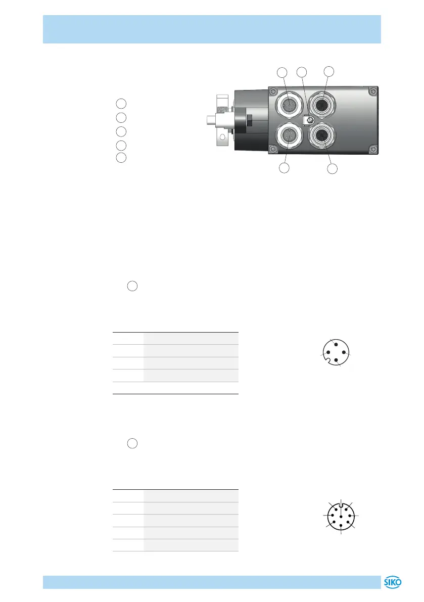
Fig. 7: Pin assignment
1
2
3
4
5
1
Port1
2
Port2
3
Operating voltage
4
PE-connection
5
Digital inputs / outputs
Data transmission via Ethernet
The line length between two nodes must not exceed 100 m. Use only Eth-
ernet cables which correspond at least to category 5 (CAT 5) acc. to EN
50173 or ISO / IEC 11801. Use only cables with complete shield.
Operating voltage pin configuration
•
3
Operating voltage 4-pole pin M12 A-coded (Fig. 7).
For accessory mating connectors and cable extensions refer to chapter 8.
PIN Designation
1 +UB (output stage )
2 +UB (control)
3 GND (output stage)*
4 GND (control)*
* internally linked with SGND
Strand cross section of the lines: 0.5mm².
Digital inputs / outputs pin configuration
•
5
Digital inputs / outputs 8-pole pin M12 A-coded (Fig. 7).
For accessory mating connectors and cable extensions refer to chapter 8.
PIN Designation
1 input 1
2 input 2
3 input 3
4 input 4
5 output 1
viewing side = plug-in side
Buchse
Stecker
M12 A-Codiert 5-pol. (CAN)
1
4
5
2
3
2
3
1
5
4
Buchse
Stecker
M12 B-Codiert 5-pol. (Profibus)
2
34
1
3
2
5
4
1
5
8
7
6
5
4
3
2
1
Buchse
Stecker
M12 A-Codiert 8-pol.
2
1
7
6
4
3
8
Buchse
Stecker
M8 4-pol.
3
4
1
2
1
2
3
4
4
2
3
2
3
1
4
1
M12 A-Codiert 4-pol.
Stecker
Buchse
7
2
3
4
5
6
1
Buchse
Stecker
M16 A-Codiert 7-pol.
6
1
2
34
5
7
M12 D-Codiert 4-pol.
Buchse
2
34
1
8
7
6
5
4
3
2
1
Buchse
Stecker
M12 A-Codiert 8-pol.
2
1
7
6
5
4
3
8
viewing side = plug-in side
 Loading...

