AG25
Installation English
AG25 · Date 19.07.2022 · Art. No. 87450 · Mod. status 157/22
32
Inrush current, destruction of contacts
The contacts of operational voltage on the actuator have no starting cur-
rent limitation. Owing to internal capacitances, the starting current can
be a multiple of nominal current. If operational voltage is switched on vai
switching of contacts, the contacts can be destroyed or welded together.
` Use a power pack which limits the peak value of output current to a
value admissible for the contact.
` Switch power input of the power pack rather than output voltage.
Electromagnetic compatibility (EMC)
The following measures are required in order to ensure the actuator's elec-
tromagnetic compatibility:
` Provide a separate power adapter for the supply of one or multiple
SIKO actuators.
` All lines for connecting the actuator must be shielded.
` The cable shield must be applied to both sides.
` The drive is to earthed via the flat connection with a strand section of
at least 2.5 ... 4mm².
Basically, all connections are protected against external interference.
Choose a place of operation that excludes inductive or capacitive interfer-
ence influences on the actuator. When mounting the system keep a maxi-
mum possible distance from lines loaded with interference. If necessary,
provide additional installations including screening shields or metallized
housings.
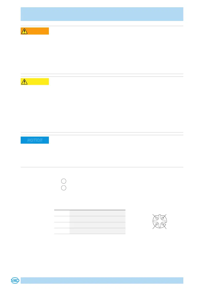
Ethernet pin configuration
•
1
Port1: socket 4-pole M12 D-coded (Fig. 7).
•
2
Port2: socket 4-pole M12 D-coded (Fig. 7).
For accessory mating connectors and cable extensions refer to chapter 8.
PIN Designation
1 Tx+
2 Rx+
3 Tx-
4 Rx-
M12 D-Codiert 4-pol.
Buchse
2
34
1
viewing side = plug-in side
Port1 und Port2
 Loading...

