AP04
Installation English
AP04 · Date 19.05.2016 · Art. No. 84211 · Mod. status 154/16
26
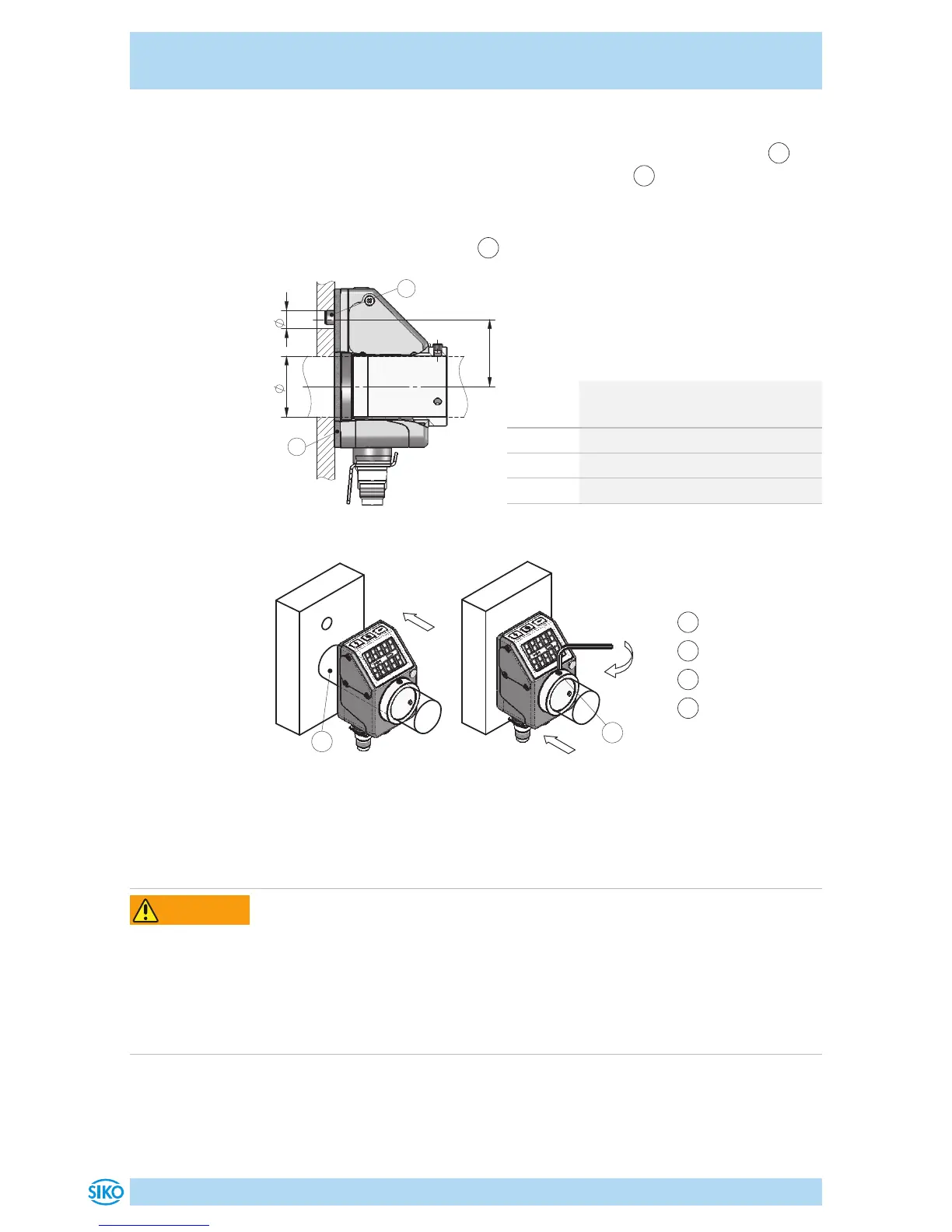
Mounting (Fig. 1, Fig. 2, Fig. 3):
1. Push the position indicator inclusive sealing plate onto the shaft
3
until reaching the stop. Insert torque support
2
into the existing bore
(non-distorted mounting). A long hole for the torque support is recom-
mended.
2. Tighten grub screws M3
4
with max. 0.2Nm.
Fig. 1: Mounting dimensions
dim. ød ø6 (type A)
ø10
+0.8
(type B)
dim. L1 22
dim. øD ø20
(clearance fit)
dim. øD ø14 (clearance fit / Protection IP65rd)
Tab. 1: Mounting dimensions
1
Sealing plate
2
Torque support
3
Shaft
4
Grub screw
Fig. 2: Mounting
Fig. 3: Fastening torque
for screws
4.2 Electrical Installation
Destruction of parts of equipment and loss of regulation control
` All lines for connecting the position indicator must be shielded.
` Do not disconnect or close live connections.
` Perform wiring work in the de-energized state only.
` Use strands with suitable ferrules.
` Check all lines and plug connections before switching on the device.
WARNING
 Loading...