AP04
Installation Deutsch
AP04 · Datum 19.05.2016 · Art. Nr. 84211 · Änd. Stand 154/16
7
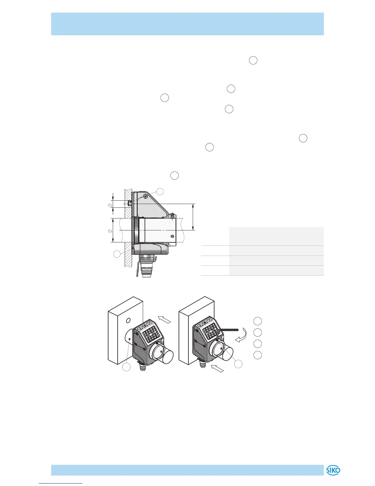
Vorbereitung Montage (Abb. 1, Abb. 2, Abb. 3):
1. Beiliegende selbstklebende Dichtungsplatte
1
(Moosgummi) auf
Lagerbügel beziehungsweise Zwischenplatte aufkleben (Sicherstel-
lung der Schutzart, ausgleichen von Unebenheiten).
2. Bohrung (ød) für Drehmomentstütze
2
auf Abstand (L1) zur
Antriebswelle
3
fertigen.
3. Durchmesser (øD) der Antriebswelle
3
beachten.
Montage (Abb. 1, Abb. 2, Abb. 3):
1. Positionsanzeige inkl. Dichtungsplatte bis Anschlag auf Welle
3
schieben. Drehmomentstütze
2
in vorhandene Bohrung einführen
(verspannungsfreie Montage). Eine Langloch für die Drehmoment-
stütze wird empfohlen.
2. Gewindestifte M3
4
mit maximal 0.2Nm anziehen.
Abb. 1: Einbaumaße
 Loading...