1 MACHINE DESCRIPTION
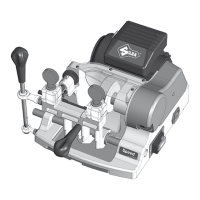
SPEED is a professional cutting machine for at keys used with cylinder, car locks and cruciform.
Standard only on
120V version
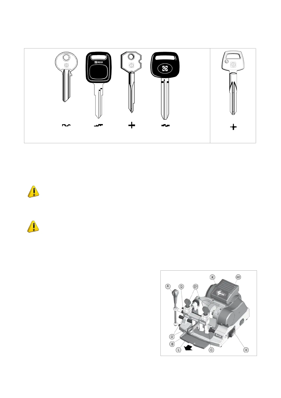
Fig.3
The main parts of the machine are described below:
• Main switch
The key-cutting machine is connected to a power socket provided with a differential switch; when the machine is
turned on by means of the switch (H) located on its right-hand side, the warning light (H1) comes on to show that
the machine is live.
ATTENTION: switch (H) is electromagnetic, in the event of a power failure it goes out
automatically. When electricity is restored it must be reset manually to power the machine
again by means of the plug.
• Motor start-up switch
On the left-hand side of the motor there is the motor start switch (K).
ATTENTION: the illuminated switch remains on to indicate that the key-cutting machine has
been started (cutter in motion).
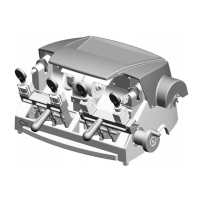
• Motor and transmission unit
Motor transmission takes place by belt. On the right-hand side of the motor there is the transmission shaft which
moves the cutting tool (F) and the brush (S) (see Fig.5). These components are protected by:
-
cutting tool cover (N)
-
brush cover (P)
• Clamp carriages
The horizontal carriage (C) controlled by lever (A) has a handle
(B) for front movement and holds 2 clamps (D).
The carriage is so designed as to avoid accumulation of dust or
cutting swarf.
The machine is designed with a ramp along which chippings can
fall into the special chippings tray (L) placed under the carriage
and easily removable for emptying and cleaning.
Fig.4
Operating manual SPEED
Copyright Silca 2013
4