6.7 Replacing the main switch
ATTENTION: remove the mains plug.
1) Access the lower compartment (see chap.6.6).
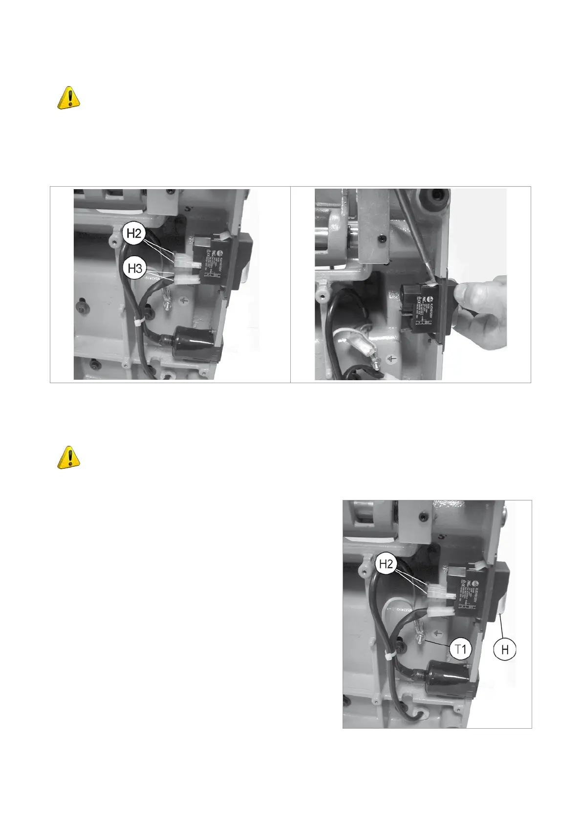
2) Detach the 4 connectors (H2) and (H3) paying special attention to their position (Fig.36).
3) Remove the switch making pressure on the tabs with a screwdriver (Fig.37).
4) Fit the new main switch.
5) Reconnect the 4 connectors (H2) and (H3).
Fig.36 Fig.37
6.8 Replacing the motor
ATTENTION: remove the mains plug.
1) Access the lower compartment (see chap.6.6).
2) Disconnect the 2 connectors (H2). Loosen the nut (T1) and
disconnect the earthing wire (Fig.38).
3) Remove the wire tie.
4) Loosen and remove the 4 motor xing nuts (Fig.39).
5) Re-position the machine on the workbench.
6) Remove the screws (P1), then the protective cover (P) (Fig.40).
7) Unscrew the wire grommet (M3) (Fig.41).
8) Remove the 4 motor xing screws (M1) and pull off the belt.
9) Loosen the grub screw (S1) and remove the drive pulley
(Fig.42).
10) Pull out the motor cable and remove the motor (Fig.43).
11) Fit the new motor, the 4 screws (M1) and 4 nuts (M4).
12) Fit the drive pulley onto the new motor and secure with the grub
screw (S1).
13) Fit the belt and adjust tension, tighten the 4 screws (M1) and 4
motor xing nuts (M4).
Fig.38
Operating manual SPEED
Copyright Silca 2013
23