GDM-5411
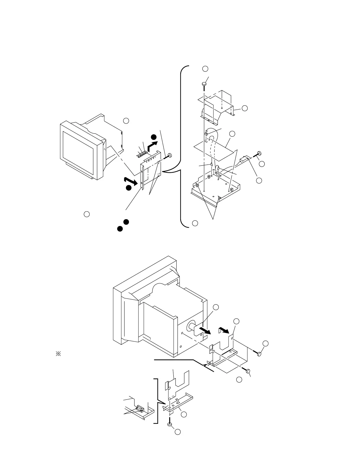
2-3. G BOARD REMOVAL
2-4. A BOARD, I/O TERMINAL BOARD ASSEMBLY REMOVAL
2-2
Two screws
(+ BVTT 4 x 8)
Two hooks
G shield
G board
GND
CN602
CN654
CN653
CN652
CN650
GND
Open the G block in the direction
of the arrow . and remove of
the arrow .
A
B
Two printed circuit board holders
A
B
6
2
1
Two screws
(+ BVTP 3 x 8)
7
AC inlet (3P)
8
3
4
5
Four screws
(+BVTP 3 x 8)
A board (2/2)
Screw (M4)
(EXT tooth washer)
2
Three screws
(+BVTT 4 x 8)
1
Two screws
(HD15)
5
I/O terminal board assembly
6
4
A board (1/2)
A board (1/2)
A board (1/2)
Screw lock
3
When installing I/O terminal
board assembly, be sure to apply
screw lock on 2 spots after
screws (HD15) are fixed.
 Loading...