GDM-5411
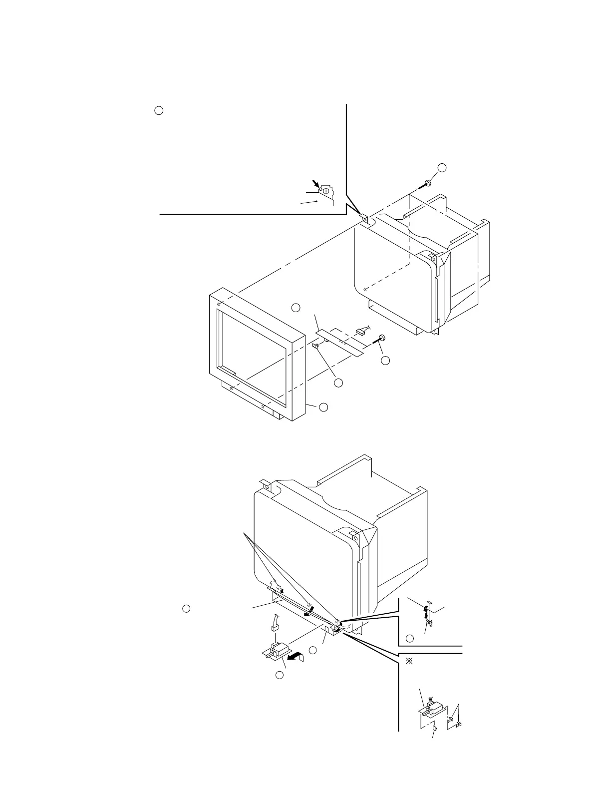
2-7. BEZEL ASSEMBLY, H BOARD REMOVAL
2-8. J BOARD REMOVAL
2-4
Degaussing coil holder
J board
Two hooks
J board
Claw
2
3
1
Claw
4
Three degaussing
coil holders
Degaussing coil
CN891
When installing J board, put the
behind of the board in two hooks.
Four screws
(Tapping screw 5)
H board
Two screws
(+ BVWHTP 3 x 12)
Bezel assembly
2
Before removing the bezel assembly, secure
the picture tube by attaching two screws to
the picture tube shield at the positions
shown with an arrow (diagonal two places)
to prevent the picture tube from falling. (Use
the screws +BVTT 4 x 8 that fix top cover.)
1
3
4
5
Input selection
switch cap
6
CN801
Picture tube shield
 Loading...