GDM-5411
HV Regulator
Circuit Check
HV Protector
Circuit Check
Beam Current
Protector Circuit
Check
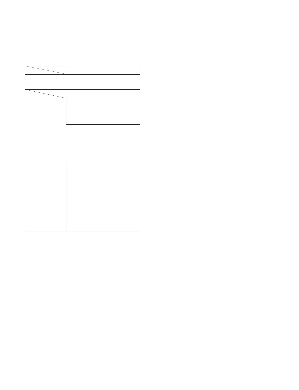
When replacing or repairing the shown below table, the
following operational checks must be performed as a
safety precaution against X-rays emissions from the unit.
SECTION 3
SAFETY RELATED ADJUSTMENT
3-1
Part Replaced ([)
RV901
HV ADJ
* Confirm one minute after turning on the power.
a) HV Regulator Circuit Check
1) Enter black crosshatch signal (black on white back-
ground), and check that high voltage is in the speci-
fied range.
[Specification]: 27.00 ± 0.10 kV
2) Check that the voltage of D912 cathode on the D
board is 27.0 V or more.
b) HV Protector Circuit Check
1) Enter black crosshatch signal (black on white back-
ground).
2) Apply the specified voltage to the D912 cathode on
the D board, and check that high voltage is 0.1 kV or
less.
[Specification]: 31.90 + 0.00/– 0.05 V
c) Beam Current Protector Circuit Check
(1st Protector): D Board
1) Apply 4.5 V DC to CN504 0 pin on the D board,
and check high voltage value.
2) Connect constant current source to a section between
T902 (FBT) qa pin and qs pin (GND) on the D
board, and check that high voltage checked in 1)
lowers by 1.50 kV or more when the specified cur-
rent flows to the qa pin.
[Specification]: 2.00 + 0.00/– 0.01 mA
d) Beam Current Protector Circuit Check
(2nd Protector): D Board
1) Connect constant current source to a section between
T902 (FBT) qa pin and qs pin (GND) on the D
board, and check that the voltage of CN504 0 pin
becomes 0 V or less when the specified current flows
to the qa pin.
[Specification]: 1.70 + 0.00/– 0.01 mA
e) Beam Current Protector Circuit Check
: G Board
1) Apply 264 V AC.
2) Enter about 5 V to CN650 4 pin on the G board, and
check that the output voltage of CN653 2 pin is
about 15 V.
3) Enter about 0 ± 0.2 V to CN654 4 pin, and check
that the output voltage of CN653 2 pin becomes 1.0
V or less.
f) Beam Current Protector Circuit Check
: N Board
1) Check that the protector operates, when the voltage
of CN010 qh pin on the N board is lowered to 0 V or
less (for more than 2 seconds).
Part Replaced (])
D Board C920, IC901, R923
R924, R929, R945,
RV901, T902 (FBT)
• Mounted D Board
D Board C922, C925, C926,
D912, D914, D915,
D921, Q907, Q908,
R921, R922, R932,
R937, R939, T902 (FBT)
• Mounted D Board
D Board C910, C921, C933,
D901, D902, D913,
IC503, IC901, R901,
R920, R928, R930,
R931, R940, R941,
T902 (FBT)
• Mounted D Board
G Board IC652
• Mounted G Board
N Board IC001, R031, R032
• Mounted N Board
 Loading...