Smart Machine Smart Decision
SIM7020_Hardware_Design_V1.02 13 2018-07-25
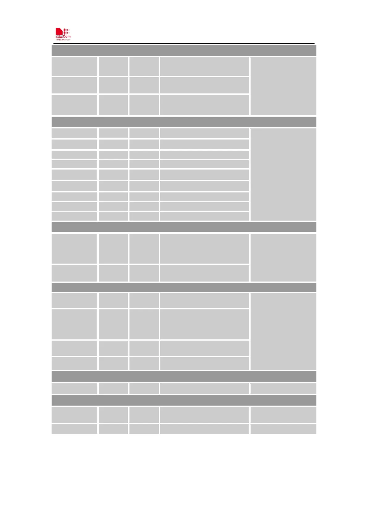
USB
USB_VBUS 24 DI,PD
Valid USB detection input with
2.5~5.25V detection voltage
USB interface for
debugging
USB_DP 25 I/O
Positive line of the differential,
bi-directional USB signal.
USB_DN 26 I/O
Negative line of the differential,
bi-directional USB signal.
UART interface
UART1_TXD 1 DOH Transmit Data
If unused, keep them
open.
UART1_RXD 2 DI, PU Receive Data
,
UART1_DCD 5 DOH Data carrier detect
UART1_DTR 6 DI, PU Transmit Data
,
Indicate and Control in PSM Mode
RTC_GPIO0 11 DO
change state from low to high if
RTC_EINT receive interrupt
event.
Voltage Domain:
VB AT
RTC_EINT 12 DI 、
RTC_EINT can be the wake up
source for exiting PSM.
NETLIGHT 41 DO
LED control output as network
status indication.
If unused, keep them
open.
S TAT U S 42 DO
High level: Power on and
firmware ready
GPIO0 10 IO
Do not pull down before power
on
GPIO1 29 IO
RF interface
ANT 32 AI antenna
Other interface
ADC 38 AI
Analog-digital converter input.
Voltage range: 0.1
-
If unused, keep them
open.
NC 20
No connection.
Keep it open