Smart Machine Smart Decision
SIM7020_Hardware_Design_V1.02 24 2018-07-25
3 ON Semi ESD9L5.0ST5G TVS 5V 0.5PF 150mW RO SOD-923
4 TOSHIBA DF2S6.8UFS TVS 5V 2PF 150mW RO SOD-923
3.7 SIM Interface
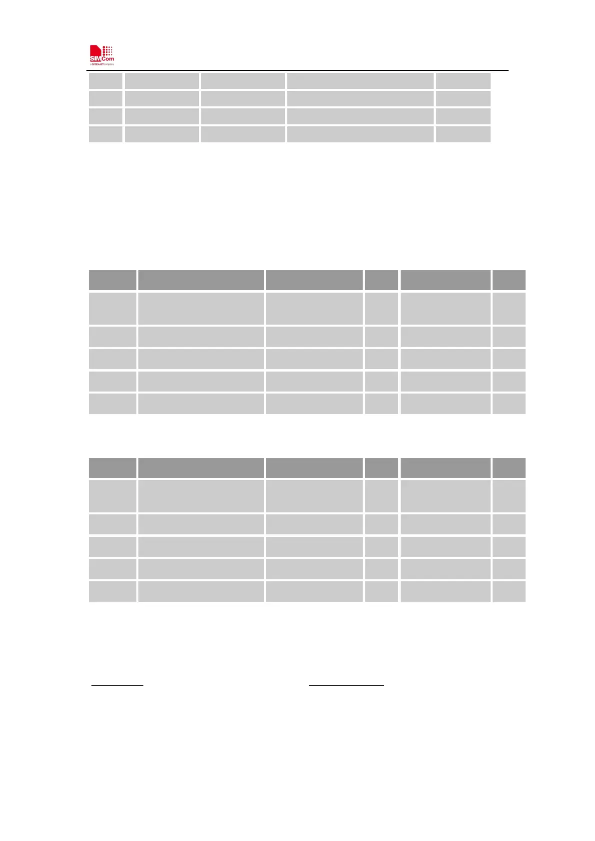
SIM7020 supports both 1.8V and 3.0V SIM Cards.
Table 12: SIM electronic characteristic in 1.8V mode (SIM_VDD=1.8V)
Symbol Parameter
Min. Typ. Max. Unit
SIM_V
DD
LDO power output voltage
1.75 1.8 1.95 V
V
IH
High-level input voltage
0.65*SIM_VDD - SIM_VDD +0.3 V
V
IL
Low-level input voltage
-0.3 0 0.25*SIM_VDD V
V
OH
High-level output voltage
SIM_VDD -0.45 - SIM_VDD V
V
OL
Low-level output voltage
0 0 0.45 V
Table 13: SIM electronic characteristic 3.0V mode (SIM_VDD=3V)
Symbol Parameter
Min. Typ. Max. Unit
SIM_V
DD
LDO power output voltage
2.75 3 3.05 V
V
IH
High-level input voltage
0.65*SIM_VDD - SIM_VDD +0.3 V
V
IL
Low-level input voltage
-0.3 0 0.25*SIM_VDD V
V
OH
High-level output voltage
SIM_VDD -0.45 - SIM_VDD V
V
OL
Low-level output voltage
0 0 0.45 V
3.7.1 SIM Application Guide
It is recommended to use an ESD protection component such as ESDA6V1W5 produced by ST
(www.st.com ) or SMF15C produced by ON SEMI (www.onsemi.com
). Note that the SIM
peripheral circuit should be close to the SIM card socket. The following figure shows the 6-pin
SIM card holder reference circuit.