Smart Machine Smart Decision
SIM7020_Hardware_Design_V1.02 22 2018-07-25
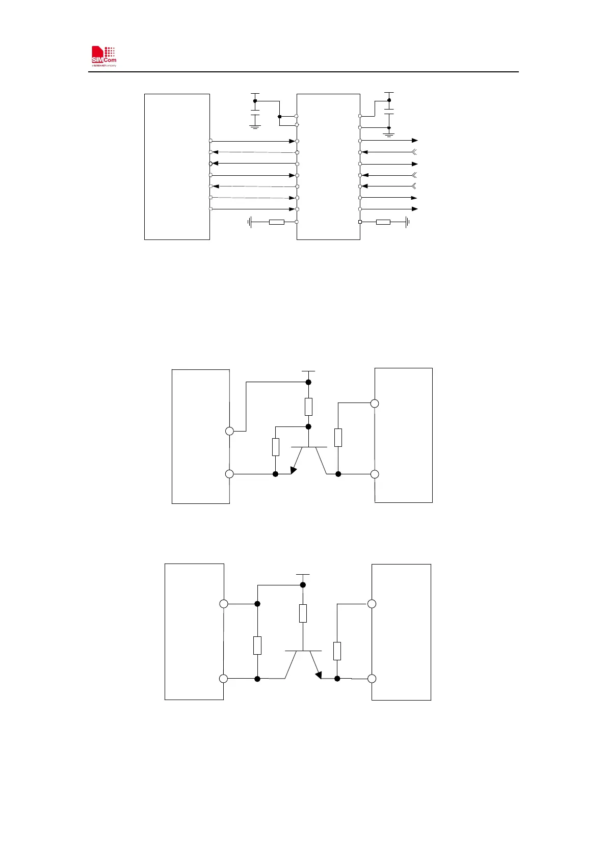
TXD
RXD
RTS
CTS
DTR
DCD
RI
A7
A1
A2
A3
A4
A5
A6
MODULE
TXB0108 RGYR
UART
A8
B7
B1
B2
B3
B4
B5
B6
B8
VCCA
OE
VDD_ EXT
100nF
3.3V
100nF
VCCB
GND
TXD_3.3V
RXD_3.3V
RTS_3.3V
CTS_3.3V
DTR_3.3V
DCD_3.3V
RI_3.3V
47K 47K
Figure 12: Reference circuit of level shift
Note: When it uses the level shifter IC, the pullupresistance
on TXD_3.3V
DCD_3.3V should not be less than 47KΩ.
Also the following reference circuit is recommended:
VDD_EXT
4.7K
47K
UART1_TXD
4.7K
GSM
VDD_EXT
RXD
VDD
DTE
Figure 13: TX level matching circuit
VDD_EXT
4.7K
47K
4.7K
DTE
UART1_RXD
GSM
VDD_EXT
TXD
VDD
Figure 14: RX level matching circuit
Note: The default band rate is 115200bps. The triode conversion circuit is not suitable for high
band rate more than 460800. When using UART2 for downloading software, the band rate is
921600bps, please pay attention to the device’s speed support.