Smart Machine Smart Decision
SIM7020_Hardware_Design_V1.02 16 2018-07-25
3 Interface Application
3.1 Power Supply
The power supply for SIM7020 must be able to provide sufficient current up to more than 500mA
in order to satisfy the power supply current for maximum consumption.
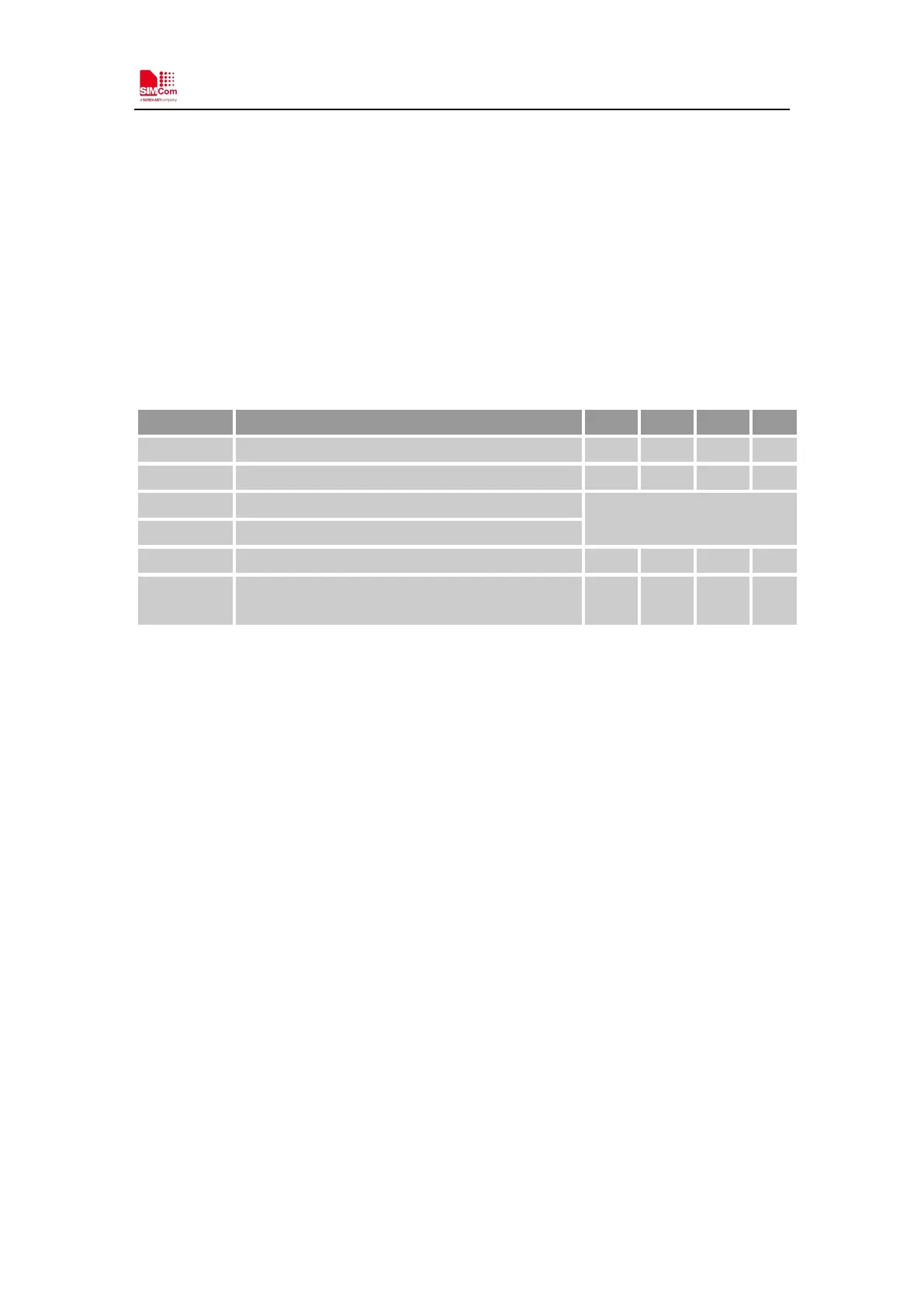
Table 6: VBAT pins electronic characteristic
VB AT Module power voltage 2.1 3.3 3.6 V
I
Module power peak current in NB emission 500 - - mA
I
Module power average current in normal mode
Please refer to the table 32
I
VBAT(sleep)
Power supply current in sleep mode
I
VBAT(PSM)
Power supply current in PSM mode - 3.4 - uA
I
VBAT(power-of
Module power current in power off mode. - - 12 uA
3.2 Power Supply Design Guide
Make sure that the voltage on the VBAT pins will never drop below 2.1V, or module will be work
abnormally.
Note: If the power supply for VBAT pins can support up to500mA, using a total of more than
100uF capacitors is recommended, or else users must using a total of 300uF capacitors typically,
in order to avoid the voltage drop. The module power peak current depends on the total
capacitance. Using a total of 1000uF capacitors in the test that will reduce the peak current to
320mA.
The following figure shows the recommended circuit .These capacitors should be put as close as
possible to VB AT pads. Also, users should keep VBAT trace on circuit board wider than 1 mm to
minimize PCB trace impedance.