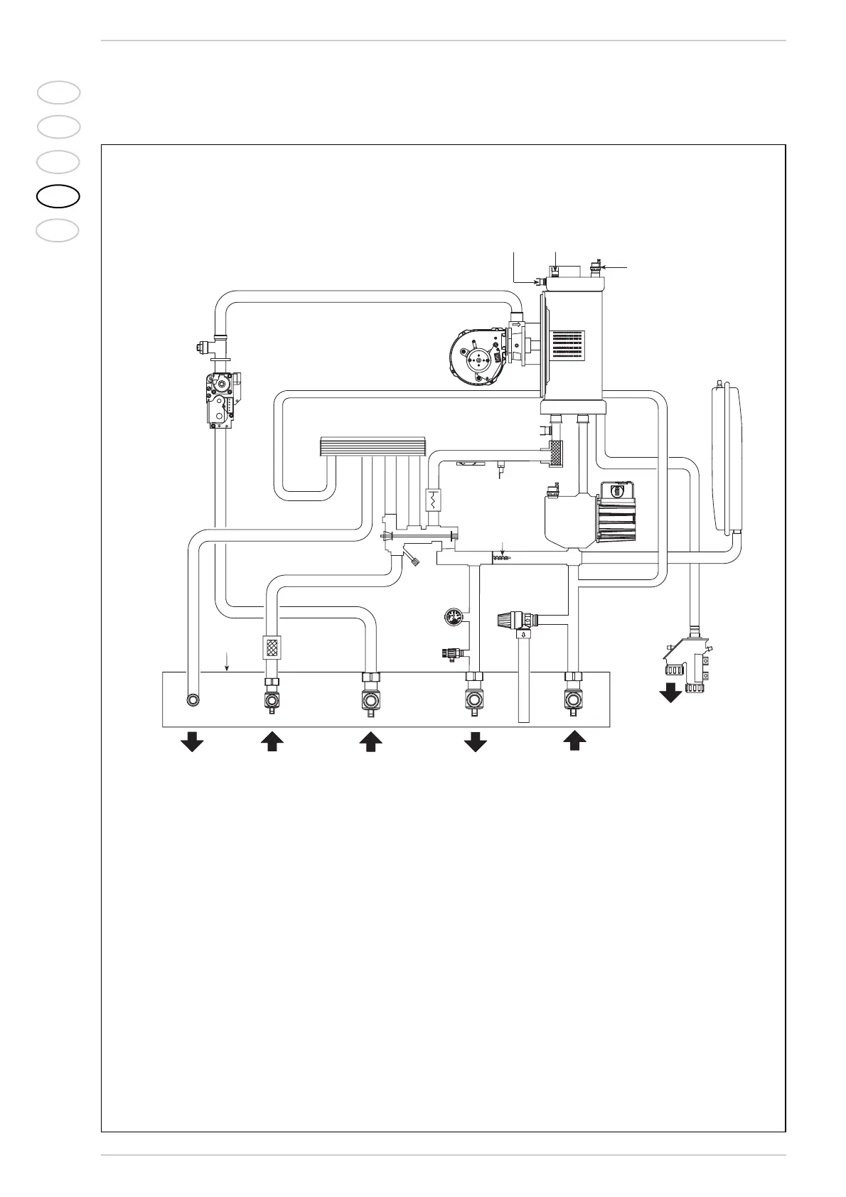
1.4 FUNCTIONAL DIAGRAM
Fig. 2
KEY
1Fan
2 Air/gas mixer
3 Water-gas exchanger
4 Gas rate adjuster
5 Gas valve
6 D.H.W. exchanger
7 Diverter valve with charging
8 Flowmeter
9 Thermometer probe
10 C.H. sensor (SM)
11 Aqua Guard Filter System
12 100°C safety stat
13 Automatic air vent
14 Circulation pump
15 Automatic by-pass
16 Heat water gauge
17 Boiler discharge
18 Safety valve
19 Expansion vessel
20 Condensation water trap
21 Upper automatic air vent
22 90°C limit stat
23 D.H.W. filter
24 Fixing jig
25 D.H.W. cock (optional)
26 Gas cock (optional)
27 C.H. flow cock (optional)
28 C.H. return cock (optional)
29 95°C smoke stat