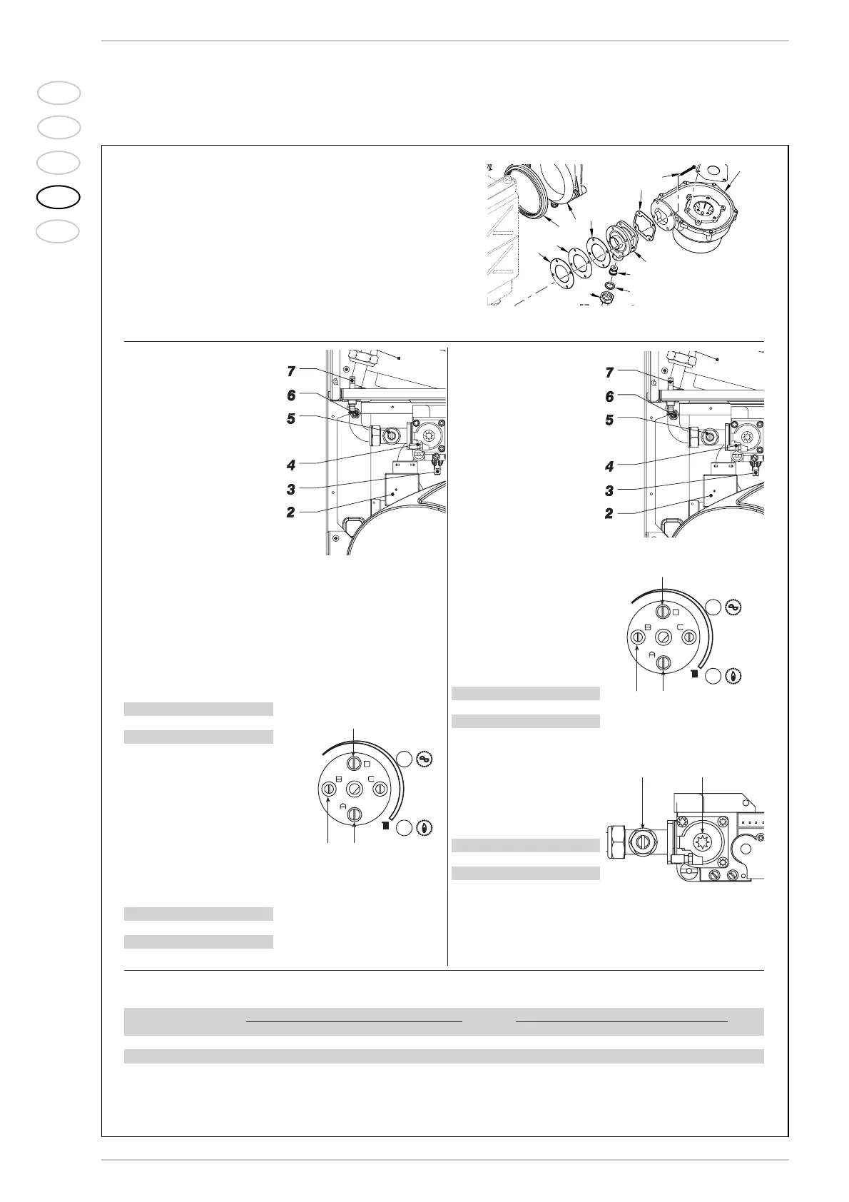
AIR CALIBRATION
Electrically disconnect the hea-
ting probe (SM) and connect
the wires to another similar
free probe. Turn the heating
potentiometer knob to the
maximum setting, remove the
knob and connect the differen-
tial manometer (+ sign) to the
air pressure intake [7 - Drawing
1].
Sequence of operations:
1) Turn the heating power trim-
mer anticlockwise to the
bottom of the scale B [6 -
Drawing 2].
2) Calibrate the air signal using
the minimum fan power
adjustment trimmer A [4 -
Drawing 2] to obtain the
figure in mmH
2O shown in
the table:
3) Turn on a hot water tap to
bring the boiler up to maxi-
mum hot water power.
4) Calibrate the air signal using
the maximum fan power
adjustment trimmer D [2 -
Drawing 2] to obtain the
figure in mmH
2
O shown in
the table:
GAS CALIBRATION
Connect the differential mano-
meter (+ sign) with decimal
scale in mm or Pascal to the
gas intake [6 - Drawing 3].
Sequence of operations:
1) Turn the heating power adju-
stment trimmer anticlockwi-
se to the bottom of the
scale B [6 - Drawing 4].
2) Fully open the gas capacity
step [7 - Drawing 5]
3) Calibrate gas pressure
using the OFF-SET adjust-
ment screw [8 - Drawing 5]
to obtain the figure in
mmH
2
O shown in the table:
4) Close the gas capacity step
[7 - Drawing 5] to obtain the
figure in mmH
2
O shown in
the table:
After completion of calibration operations, check CO
2
values using a combustion analyser. If discrepancies are found with respect to the
values appearing in the tables, correct as necessary:
– Use the OFFSET screw (
8 – Drawing 5
) to correct CO
2
at “MIN” output.
– Use the capacity step to correct CO
2 at “MAX” output (
7 – Drawing 5
).
25 BF 30 BF
G20 13,0 13,0
G31 13,0 13,0
“Format Dewy.zip 25 BF” “Format Dewy.zip 30 BF”
CO
2
(Methane) CO
2 (Propane) CO
2
(Methane) CO
2
(Propane)
“MIN” power 9,0 ±0,3 9,9 ±0,2 9,0 ±0,3 9,9 ±0,2
“MAX” power 9,0 ±0,3 9,9 ±0,2 9,0 ±0,3 9,9 ±0,2
GAS CONVERSION
– Close the gas cock.
– Replace the injector (pos. 30)
and the relevant gasket (pos.
45).
–
Cut the specified resistance on
the fan control board.
– Test for soundness all the gas
connections using soapy water
or appropriate products.
DO NOT USE NAKED FLAMES.
– Stick onto the casing panel the
plate showing the relevant fee-
ding gas.
– Proceed with air and gas cali-
bration as described below.