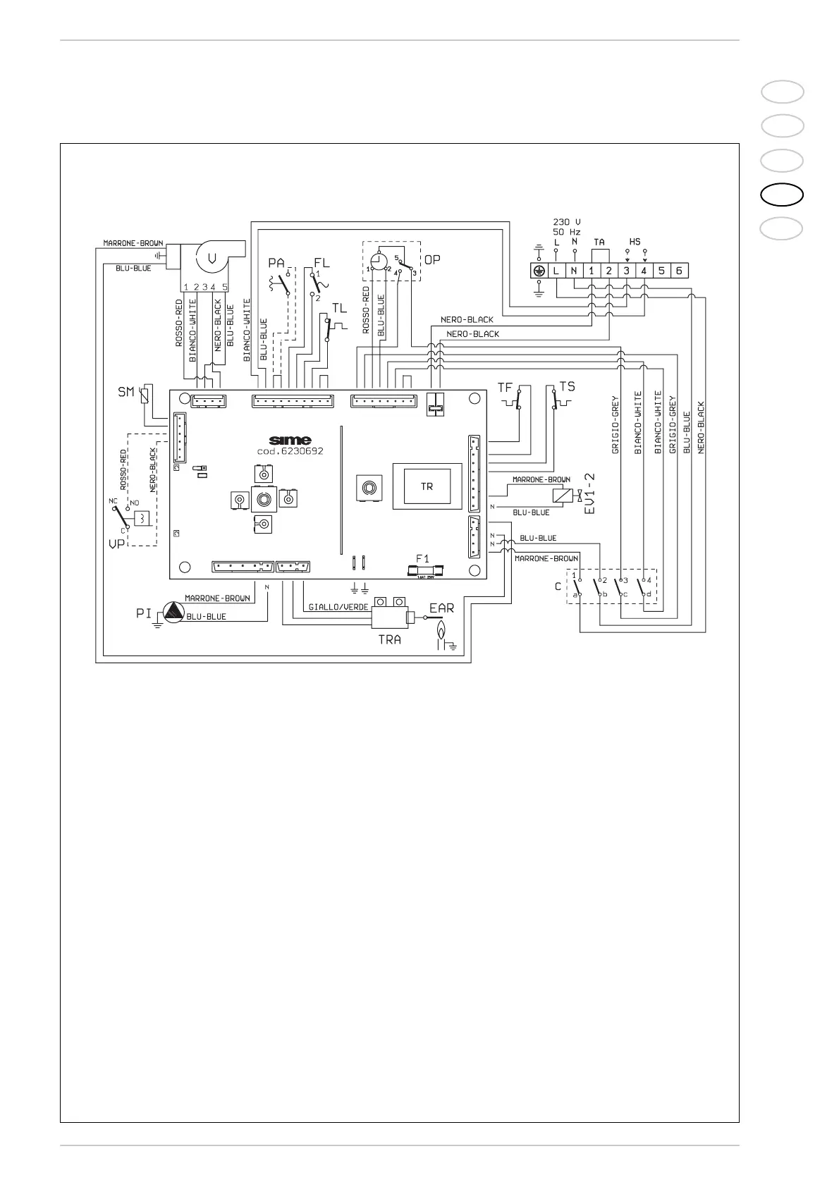
Fig. 17
2.11.3 Wiring diagram
KEY
EV1 Gas valve coil
EV2 Gas valve coil
EAR Ignition/sensing electrode
TS 100°C safety stat
VFan
PI Pump
TA Room stat
SM Sonda aquecimento
TL Termóstato límite
TR Transformer 230 - 24V
FL Flowmeter
OP Time programmer
(optional)
TF Smoke stat
VP Diverter valve with charging
TRA Ignition transformer
HS Quick fan reading
PA Water pressure gauge (is fitted)
C Selector OFF/EST/INV/RESET
Note: The room stat (TA) must be connec-
ted to the terminals 1-2.
CONNECTOR SPARE PART CODES:
J3/J10 cód. 6293570
J4 cód. 6299936
J6 cód. 6293571
J7 cód. 6293548
J9 cód. 6293574
J13 cód. 6293573