IT
ES
PT
GB
80
RUS
3.1 ELECTRONIC BOARD
The electronic boards are manufactured in
compliance with the EEC 73/23 low-voltage
directives. They are supplied with 230V.
The electronic components are guaranteed
against a temperature range of 0 to
+60°C. An automatic and continuous modu-
lation system enables the boiler to adjust
the heat output to the various system requi-
rements or the User’s needs.
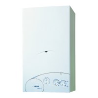
3.1.1 Fault finding
The indicator leds signalling irregular
and/or incorrect operation of the equip-
ment are indicated in fig. 16.
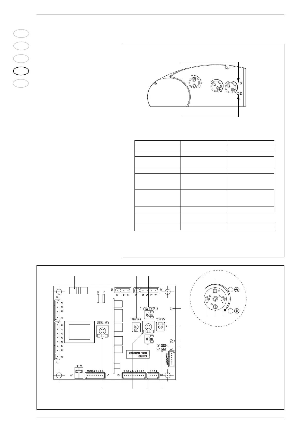
3.1.2 Devices
The electronic board is equipped with the
following devices (fig. 17):
– “POT. RISC.” trimmer (pos. 6)
Sets the maximum heating power value.
To increase the value turn the trimmer
clockwise; to reduce the value turn the
trimmer anticlockwise.
– “POT. ACC.” trimmer (pos. 3)
Trimmer to vary the pressure level upon
ignition (STEP), of the gas valve. Factory
set with 95 Hz ignition step. To increase
pressure, turn the trimmer clockwise; to
reduce pressure, turn the trimmer coun-
terclockwise. The slow ignition pressure
level can be set during the first 7
seconds following burner ignition.
After setting the pressure level upon
ignition (STEP) according to the type of
3 CHARACTERISTICS
Fig. 16
Bi-colour led 1
Bi-colour led 2
Fig. 17
KEY
1 Bi-colour led 1
2 “MAX” fan speed trimmer
3 “POT. ACC.” trimmer
4 “MIN” fan speed trimmer
5 Bi-colour led 2
6 “POT. RISC.” trimmer
7 D.H.W. potentiometer
8 Fuse (1,6 AT)
9 “JP2” connector
10 “JP1” connector
11 C.H. potentiometer
NOTE: To gain access to trimmers (2-3-4-6), unscrew the central heating potentiometer knob.
Operating mode Bi-colour led 1 Bi-colour led 2
Stand-by On green Off
Flame presence On green On orange
Flame detection
circuit fault On green Blinking orange
Ignition lock Off On red
100°C safety stat (TS)
or smoke stat (TF) Off On red
intervention
Water flow switch (FL)
or limit stat (TL) Blinking orange Off
intervention
Fan fault Blinking green Off
C.H. sensor
fault (SM) On orange Off
Boiler off Off Off