2.8
SEPARATE PIPES
When installing the pipes, follow closely
the requirements of the current stan-
dards, as well as the following practical
pointers:
– With direct intake from outside, when
the pipe is longer than 1 m, you are
recommended to insulate the piping so
as to prevent formation of dew on the
outside of the piping during particularly
hard periods of the year.
–
With the outlet pipe outside the buil-
ding or in cold indoor environments,
insulation is necessary to prevent bur-
ner failure in starting. In such cases,
provide for a condensate-collector
system on the piping.
–
If a segment of the flue passes through
a flammable wall, this segment must be
insulated with a glass wool pipe insula-
tor 30 mm thick, with a density of 50
kg/m
3
.
The maximum overall length of the intake
and exhaust ducts depends on the head
losses of the single fittings installed
(excluding the doublers) and must not be
greater than 7.00 mm H
2
O .
For head losses in the fittings, refer to
Table 2.
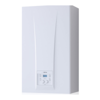
2.8.1 Separate
pipe accessories
Kit code 8093000 is supplied for this pur-
pose (fig. 11).
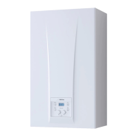
The sectored diaphragm is to be used
according to the maximum head loss
allowed in both pipes, as given in fig. 11/a.
The complete range of accessories neces-
sary for satisfying all installation require-
ments is reported in fig. 12.
76
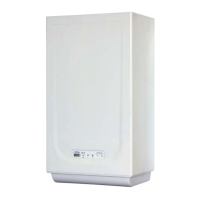
Fig. 10
KEY
1 Vertical extension L. 200
with take-off point code 8086908
2a Extension L. 1000 code 8096100
2b Extension L. 500 code 8096101
3 Tile with articulation joint code 8091300
4 Roof outlet terminal L. 1284 code 8091200
5 Supplementaty 90° elbow code 8095800
6 Supplementaty 45° elbow code 8095900
TABLE 2
Accessories ø 80 Head loss (
mm H
2
O)
Inlet Outlet Roof outlet
90° elbow MF 0,30 0,40 –
45° elbow MF 0,20 0,30 –
Extension L. 1000 (horizontal) 0,20 0,30 –
Extension L. 1000 (vertical) 0,30 0,20 –
Outlet terminal – 0,30 –
Intake terminal 0,10 – –
Doubler fitting 0,50 1,60 –
Roof outlet terminal L. 1390 – – 0,50
Tee condensation outlet – 1,00 –
Example of allowable installation calculation in that the sum of the head losses of the single fit-
tings is less than 7 mm H
2
O
Intake Outlet
7 meter horizontal pipe ø 80 x 0.20 1.40 –
7 meter vertical pipe ø 80 x 0.30 – 2.10
n° 2 90° elbows ø 80 x 0.30 0.60 –
n° 2 90° elbows ø 80 x 0.40 – 0.80
n° 1 terminal ø 80 0.10 0.30
Total head loss 2.10 + 3.20 = 5.3
mm H
2
O
With this total head loss, remove the ø 38 baffle from the intake pipe.
Fig. 11