GROUP S.P.A.
MT SB2 03
26
ENGLISH
Maximum distances and characteristics of the conductors.
Connection of the pieces of apparatus is of the non-polarised type. Use of conductors with different characteristics than the ones
prescribed does not guarantee that the system can reach certain distances or good quality of the video signal, so only use the cables
described in the following tables.
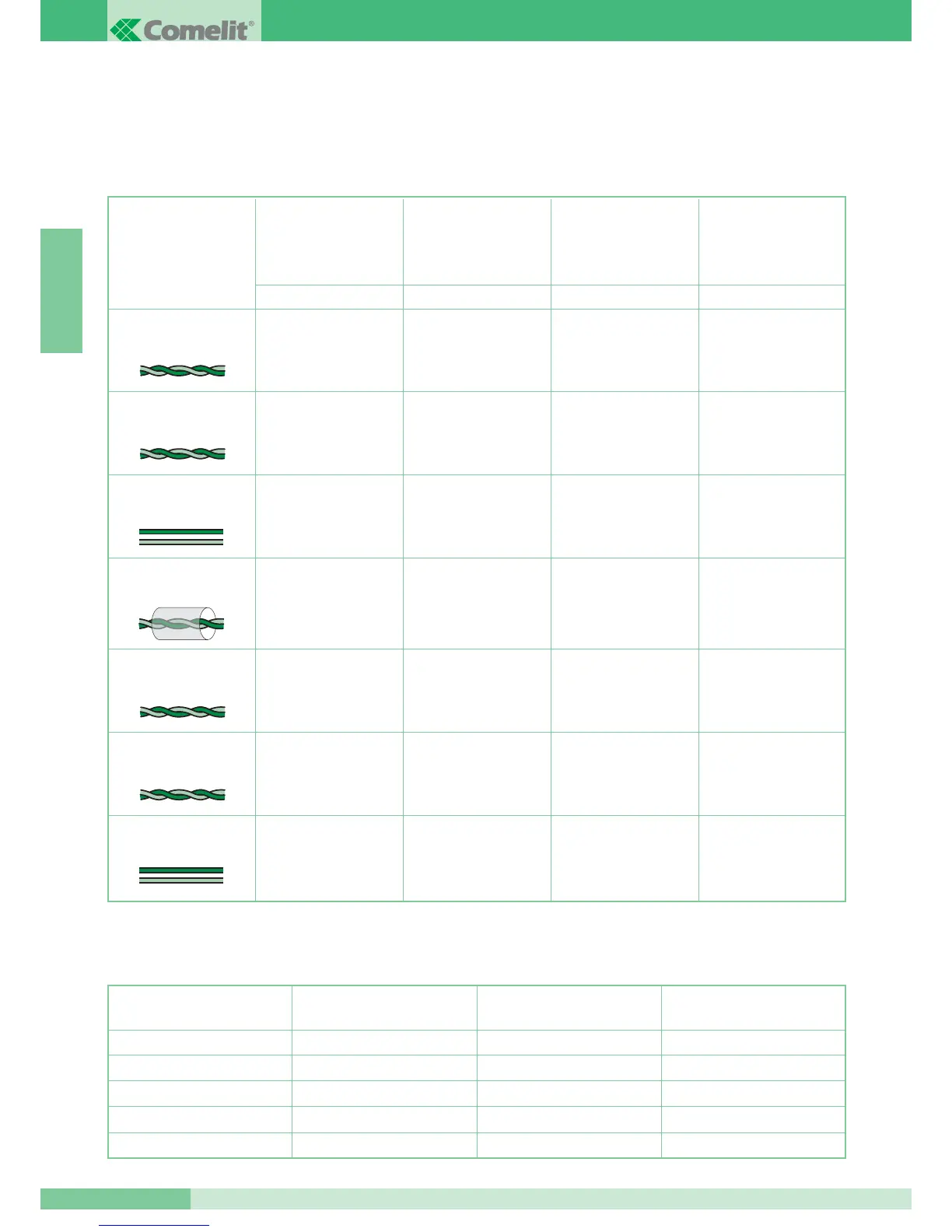
TABLE 1 distances for Simplebus1 and Simplebus2 video entry phone systems.
* When a multi-pair cable is used, only use one of the pairs available. Should it be necessary to reduce the resistive drops, use the single
pair as a single wire.
** Should a multi-core cable be used, only use two of the wires available and never use wires in parallel.
Type of cable MAX distance between
mixer 4896 and internal
extension in Simplebus2
video entry phone systems
MAX distance between
extension terminal 1214/2
and monitor
MAX distance between
4833/A or external unit
and 1214/2 in Simplebus1
video entry phone systems
MAX distance between
external unit and internal
extension in Simplebus1
systems
Twisted telephone cable cross-
sect. 0.28 mm
2
(Ø 0.6 mm)*
UTP5 cat 5 AWG 24 cable
cross-sect. 0.2 mm
2
(Ø 0.5 mm)*
ABCD
200m
X
60m
60m
X
150m
X
400m
150m 40m 100m 400m
120m 30m 80m 400m
100m 40m 150m 400m
80m 40m 150m 400m
120m 40m 100m 400m
Comelit Cable Art. 4577
cross-sect. 1 mm
2
(Ø 1.2 mm)
Comelit Cable Art. 4576 cross-
sect. 0.5 mm
2
(Ø 0.8 mm)
Two-wire cable cross-sect.
1.5 mm
2
(Ø 1.4 mm)**
Braided and shielded cable
cross-sect. 1 mm
2
(Ø 1.2 mm)*
Two-wire cable cross-sect.
0.5 mm
2
(Ø 0.8 mm)**
TABLE 2 distances for door entry phone systems.
Cross-section of the
conductor
300 m
350 m
400 m
400 m
150 m
150 m
200 m
200 m
400 m
400 m
400 m
400 m
EFG
MAX distance between external
unit and Art. 4897
MAX distance between
Art. 4897 and telephone
MAX distance between external
unit and telephone
0.28 mm
2
(
Ø
0.6 mm)
0.5 mm
2
(
Ø
0.8 mm)
1 mm
2
(
Ø
1.2 mm)
1.5 mm
2
(
Ø
1.4 mm)