GROUP S.P.A.
MT SB2 03
30
ENGLISH
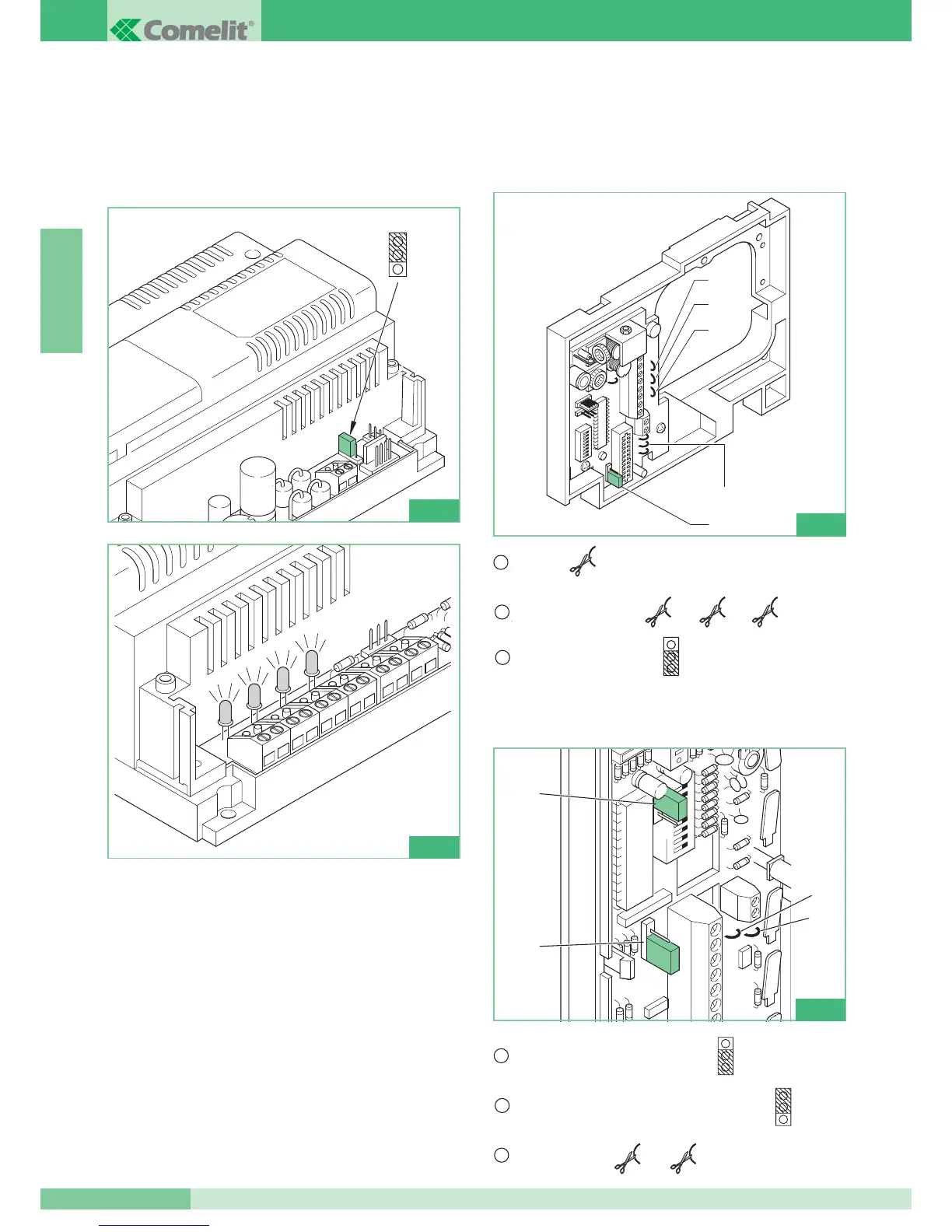
• Power the interface module Art. 4897 and start the self-learning
procedure by moving the programming Jumper (JP4) to
position B as in figure 1 and wait for the red LD1, LD2, LD3,
LD4 LEDs to stop flashing and remain lit (see fig. 2).
• Take Jumper JP4 back to position A and check that the LEDs
turn off.
• If an error should occur on one or more of the L1L1 – L2L2 –
L3L3 – L4L4 output lines during the self-learning procedure, the
DL1 – DL2 – DL3 - DL4 LED corresponding to the line the error
occurred on will remain lit, signalling the error on this line.
The errors which are found by the intercom interface during the
programming procedure are as follows:
- different user codes on the same output of Art. 4897.
- the same intercom codes on different Art. 4897 outputs.
To check configuration of the intercom network once the
procedure has been carried out, it is sufficient to connect up with
the hand-held programmer Art. 1251 and carry out configuration
reading as explained in the MT/SB2/02 Technical Manual
enclosed with Art. 1251.
HOW TO SET TELEPHONE ART. 2418W
FOR OPERATION IN SIMPLEBUS1 SYSTEMS
HOW TO SET BRACKET ART. 4714W/2I
FOR OPERATION IN SIMPLEBUS1 SYSTEMS