Page 7 579-1019 Rev M
4009 IDNAC Repeater Installation Instructions
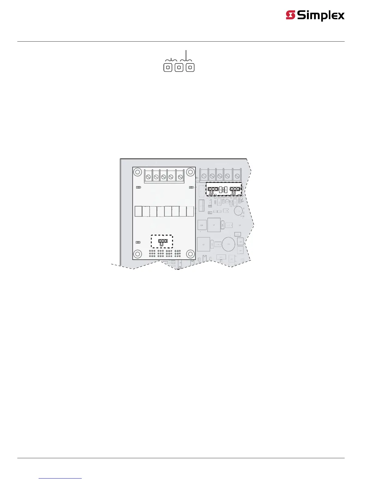
Fig 9: Wiring
Jumpers
For an extended Class A* loop:
To make the Repeater part of a Class A loop extending from a DCAI ** set the Jumper to the Class A Ext setting, jumper position 2-3.
* The Class A Adapter card must be installed on the repeater in order to use Class A wiring. The wiring jumper setting on the Class A Adapter card
must be identical to the jumper setting on the repeater. Consult the Class A Adapter manual 579-1080 for more information.
**Consult the DCAI manual 579-1029 for more information.
IDNAC IN, Built-in Line Termination Jumper, P10 Connector
This jumper is located on the main PCB at header P10. It is factory configured for OFF across P10 pins 1 and 2. It must remain in that position for
standard operation.
IIDNADNAC INC IN
++ ++
--
--
BTB1B1
CACAAC POWERAC POWERREWOP REWOP
IIDNACDNAC OUT OUT
++ ++
-- --
1
2
3
1 2 3
1 2 3
Fig 10: Wiring Jumper location, shown with a Class A adapter
Wiring overview
The Repeater doubles the EPS SLC maximum wiring distance. Wire the Repeater in either a Class A or Class B wiring configuration.
Repeater specific wiring guidelines
• A Repeater cannot be wired directly into another repeater.
• Only one Repeater can be wired as part of a Class A Loop.
• In a Class B wiring configuration using T-Tap connectors, an SLC can support up to five wiring branches that each include a Repeater.
NOTE: The Repeater does not increase the maximum number of devices supported on the IDNAC channel. The total number of devices on a
channel includes all devices present before and after the repeaters.
General wiring guidelines
• Ensure conductors test free of all grounds.
• All wiring must be done using copper conductors only, unless noted otherwise.
• The required wiring is unshielded Twisted Pair. This wiring must have a capacitive rating of less than 60pf/ft and minimum three twists (turns) per
foot.
• If shielded wire is used, the following conditions apply:
• -Ensure metallic continuity of the shield is maintained throughout the entire cable length.
-Ensure the entire length of the cable has a resistance greater than 1 megohm to earthground.
• In areas of high lightning activity, or in areas that have large power surges, use the 2081-9027 Transient Suppressor on monitor points.
• Do not run wires through elevator shafts.
• When splicing is used, ensure all spliced connections are either soldered with resin-core solder, crimped in metal sleeves, or
• encapsulated with an epoxy resin. When soldering, or crimped metal sleeves are used, insulate the junction with a high-grade electrical tape that is as
sound as the original insulating jacket. If shielded wiring is used, maintain shield continuity throughout.
• Provide a system ground for earth detection and lightning protection devices. This connection must comply with approved earth detection per
NFPA780.