Page 8 579-1019 Rev M
4009 IDNAC Repeater Installation Instructions
• Only system wiring can be run together in the same conduit.
• Ensure underground wiring is free of all water.
Device wiring guidelines
Consult the following guidelines for devices before you begin the field wiring:
• Only IDNAC devices and other compatible devices are permitted on the SLCs. Consult Compatible devices on page 18 for a list of compatible
devices.
• A maximum of six isolators between any appliance and SLC terminals is permitted. A maximum of 12 isolators for each SLC is permitted.
• A maximum of 30 devices connected directly to any isolator terminal pair is permitted.
• All wiring must be 20 AWG to 12 AWG.
• All wiring must be supervised and power-limited.
• A maximum alarm current of 3 A is permitted.
NOTE: In a Class A extension wiring configuration, the maximum loop current is limited to 3 A. In this configuration, the repeater extends
the wiring distance but does not increase the current available for the devices.
• The maximum cable load is 10,000 feet (3,048 m) per channel. The maximum wire length from the Repeater to any device is 4,000 feet (1219 m).
• The nominal voltage rating is 29 VDC.
• Follow the IDNAC Speaker Wiring Application Guidelines in document 579-1015: EPS Installation Instructions for TrueAlert ES Speaker and S/V
appliances.
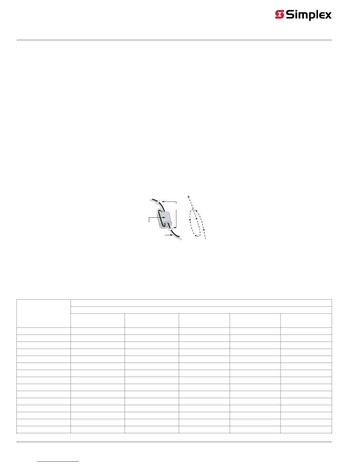
Installing ferrite beads
A ferrite bead must be installed on all wiring. To install the ferrite bead, do the following:
1. Loop the wire once though the ferrite bead close to the Repeater field wiring terminals for lowest radiated emissions before the wires leave the
box. Do not loop the ground wire on the AC wiring or the shield wire on shielded cables through the ferrite bead.
2. Secure the ferrite bead with the provided cable ties.
Loop
pattern
Cable ties
Ferrite
Bead
Fig 11: Ferrite Bead Installation
Wiring length tables
Use the following tables to calculate the maximum wiring length starting from the Repeater.
NOTE: Use Table on page 9in place of Table on page 9 for TrueAlertES Speakers and Speaker/Visible appliances.
The maximum wiring length is the shorter of the distance limits calculated by alarm current voltage drop, or by reaching the communications distance
limit.
Table 2: UTP wiring limit based on alarm current
Local and extended loop Class A wiring: Total loop length from the Repeater
Local Class B wiring: distance to the last appliance
Alarm current
20 AWG
18
AWG
16
AWG
14
AWG
12
AWG
0.050 4000 ft 4000 ft 4000 ft 4000 ft 4000 ft
0.100 2644 ft 4000 ft 4000 ft 4000 ft 4000 ft
0.150 1763 ft 2802 ft 4000 ft 4000 ft 4000 ft
0.200 1322 ft 2102 ft 3342 4000 ft 4000 ft
0.250 1058 ft 1681 ft 2674 ft 4000 ft 4000 ft
0.300 881 ft 1401 ft 2228 ft 3542 ft 4000 ft
0.350 755 ft 1201 ft 1910 ft 3036 ft 4000 ft
0.400 661 ft 1051 ft 1671 ft 2657 ft 4000 ft
0.450 588 ft 934 ft 1485 ft 2362 ft 3756
0.500 529 ft 841 ft 1337 ft 2125 ft 3380
0.750 353 ft 560 ft 891 ft 1417 ft 2254 ft
1.000 264 ft 420 ft 668 ft 1063 ft 1690 ft
1.250 212 ft 336 ft 535 ft 850 ft 1352 ft
1.500 176 ft 280 ft 446 ft 708 ft 1127 ft
1.750 151 ft 240 ft 382 ft 607 ft 966 ft