2. Install the back box.
l
See accompanying document entitled 4020 Fire Alarm Back Box lnsfallation Instructions.
. Note the restrictions for routing of Power-Limited Wiring (see Figure 1).
Note:
The installation hardware envelope contains the panel keys.
3. Mount the electronics into the back box.
l
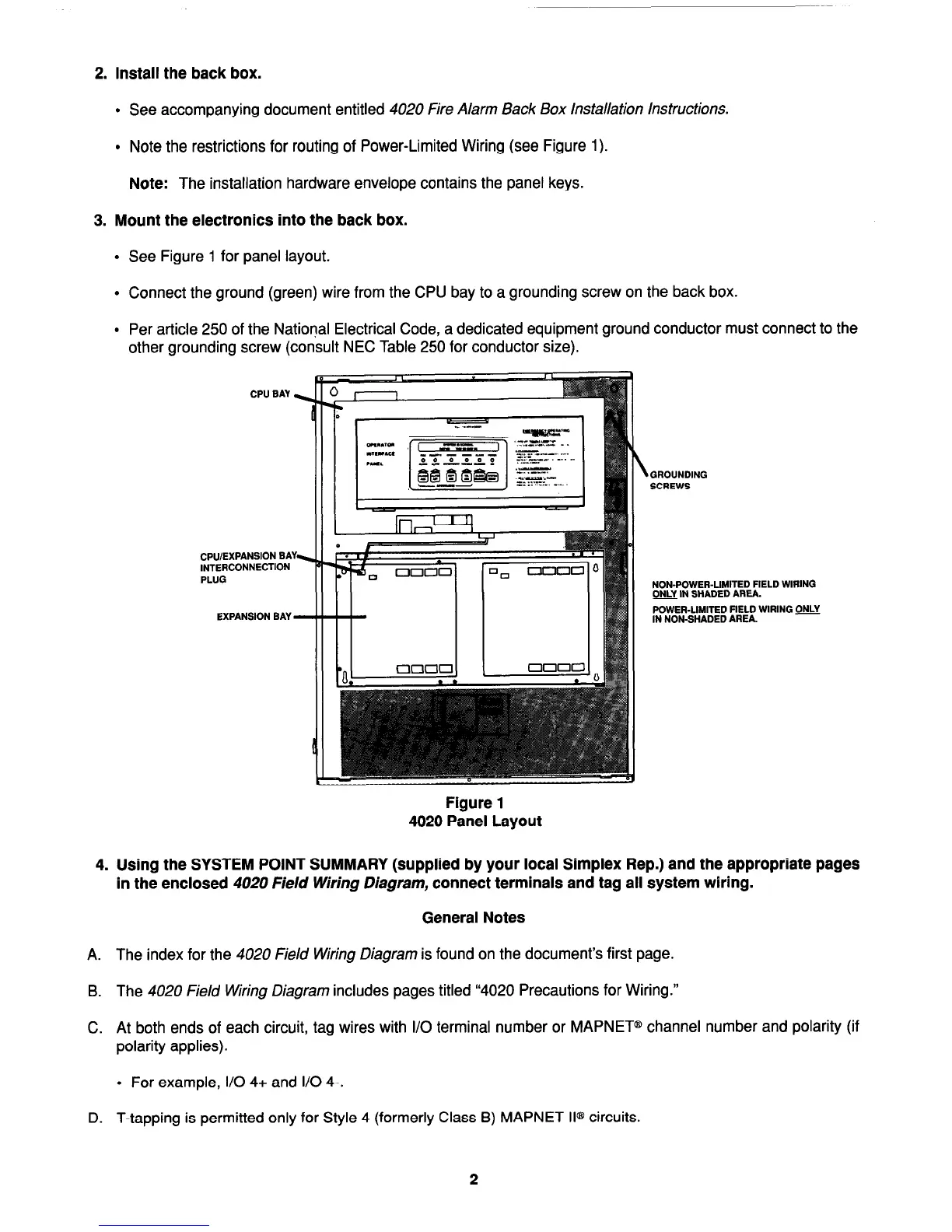
See Figure 1 for panel layout.
l
Connect the ground (green) wire from the CPU bay to a grounding screw on the back box.
l
Per article 250 of the National Electrical Code, a dedicated equipment ground conductor must connect to the
other grounding screw
(consult NEC Table 250 for conductor size).
CPU BAY z
CPU/EXPANSION BAY-
INTERCONNECTION
PLUG
EXPANSION BAY -
Figure 1
4020 Panel Layout
\
GROUNDING
SCREWS
NON-POWER-LIMITED FIELD WIRING
E IN SHADED AREA.
POWER-LIMITED FIELD WIRING ONLY
IN NON-SHADED AREA.
4. Using the SYSTEM POINT SUMMARY (supplied by your local Simplex Rep.) and the appropriate pages
in the enclosed 4020 Field Wiring Diagram, connect terminals and tag all system wiring.
General Notes
A.
The index for the 4020 Field Wiring Diagram is found on the document’s first page.
B.
The 4020 Field Wiring Diagram includes pages titled “4020 Precautions for Wiring.”
C.
At both ends of each circuit, tag wires with I/O terminal number or MAPNET@ channel number and polarity (if
polarity applies).
l
For example, I/O 4+ and I/O 4-.
D.
T-tapping is permitted only for Style 4 (formerly Class B) MAPNET II@ circuits.
2
Technical Manuals Online! - http://www.tech-man.com