________________________________________-..-----------------------------------------------------------.-----------------------------
22145559 rev: 1
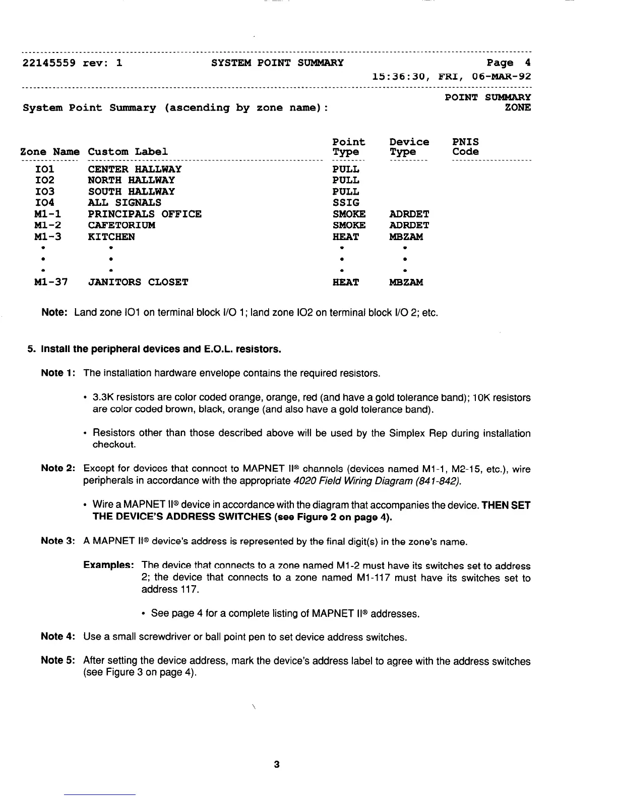
SYSTEM POINT SUMMARY Page 4
15:36:30, FRI, 06-MAR-92
POINT SUMMARY
System Point Summary (ascending by zone name): ZONE
Zone Name Custom Label
___-----_____-.
________________________________________---------------------
101
CENTER HALLWAY
102
NORTH HALLWAY
103 SOUTH HALLWAY
104 ALL SIGNALS
Ml-l PRINCIPALS OFFICE
Ml-2 CAFETORIUM
Ml-3 KITCHEN
. .
.
M;-37
.
.
JANITORS CLOSET
Point
Tw=
PULL
PULL
PULL
SSIG
SMOKE
SMOKE
HEAT
.
.
.
HEAT
Device
PNIS
Tn=e
Code
__________ _________________-___
ADRDET
ADRDET
MBZAM
.
.
.
MBZAM
Note:
Land zone 101 on terminal block I/O 1; land zone 102 on terminal block I/O 2; etc.
5. Install the peripheral devices and E.O.L. resistors.
Note 1:
The installation hardware envelope contains the required resistors.
l
3.3K resistors are color coded orange, orange, red (and have a gold tolerance band); 1 OK resistors
are color coded brown, black, orange (and also have a gold tolerance band).
l
Resistors other than those described above will be used by the Simplex Rep during installation
checkout.
Note
2: Except for devices that connect to MAPNET II@ channels (devices named Ml -1, M2-15, etc.), wire
peripherals in accordance with the appropriate 4020 Field Wiring Diagram (84 7-842).
l
Wire a MAPNET II@ device in accordance with the diagram that accompanies the device.
THEN SET
THE DEVICE’S ADDRESS SWITCHES (see Figure 2 on page 4).
Note
3: A MAPNET II@ device’s address is represented by the final digit(s) in the zone’s name.
Examples:
The device that connects to a zone named Ml -2 must have its switches set to address
2; the device that connects to a zone named Ml -117 must have its switches set to
address 117.
l
See page 4 for a complete listing of MAPNET II@ addresses.
Note
4: Use a small screwdriver or ball point pen to set device address switches.
Note
5: After setting the device address, mark the device’s address label to agree with the address switches
(see Figure 3 on page 4).
3
Technical Manuals Online! - http://www.tech-man.com