6. Check and terminate ail field wiring (see Figure 4 for terminal ‘locations).
a. Check each circuit for voltages, shorts, or opens as follows:
1. With the meter set on 3OOVAC, read the voltage across the circuit.
Meter must read 0 volts.
2. With the meter set on 60 VDC, read the voltage across the circuit again (this time in both directions).
Meter must read 0 volts.
3. With the meter set on OHMS x 10 and its (+) and (-) leads connected to the circuit’s (+) and (-) wires,
respectively, check resistance.
l
Readings must compare favorably with those shown in Figure 6 (see page 7).
Note:
if reading indicates an open in a circuit that includes a smoke detector, make sure the detector
head(s) are properly mounted and seated.
l
Circuits always read “open” (infinity) if detector power is absent and separately-powered
devices (four-wire smoke detectors) are involved.
b. Connect the wires to their terminals
in accordance with the SYSTEM POINT SUMMARY and the
appropriate field wiring diagrams.
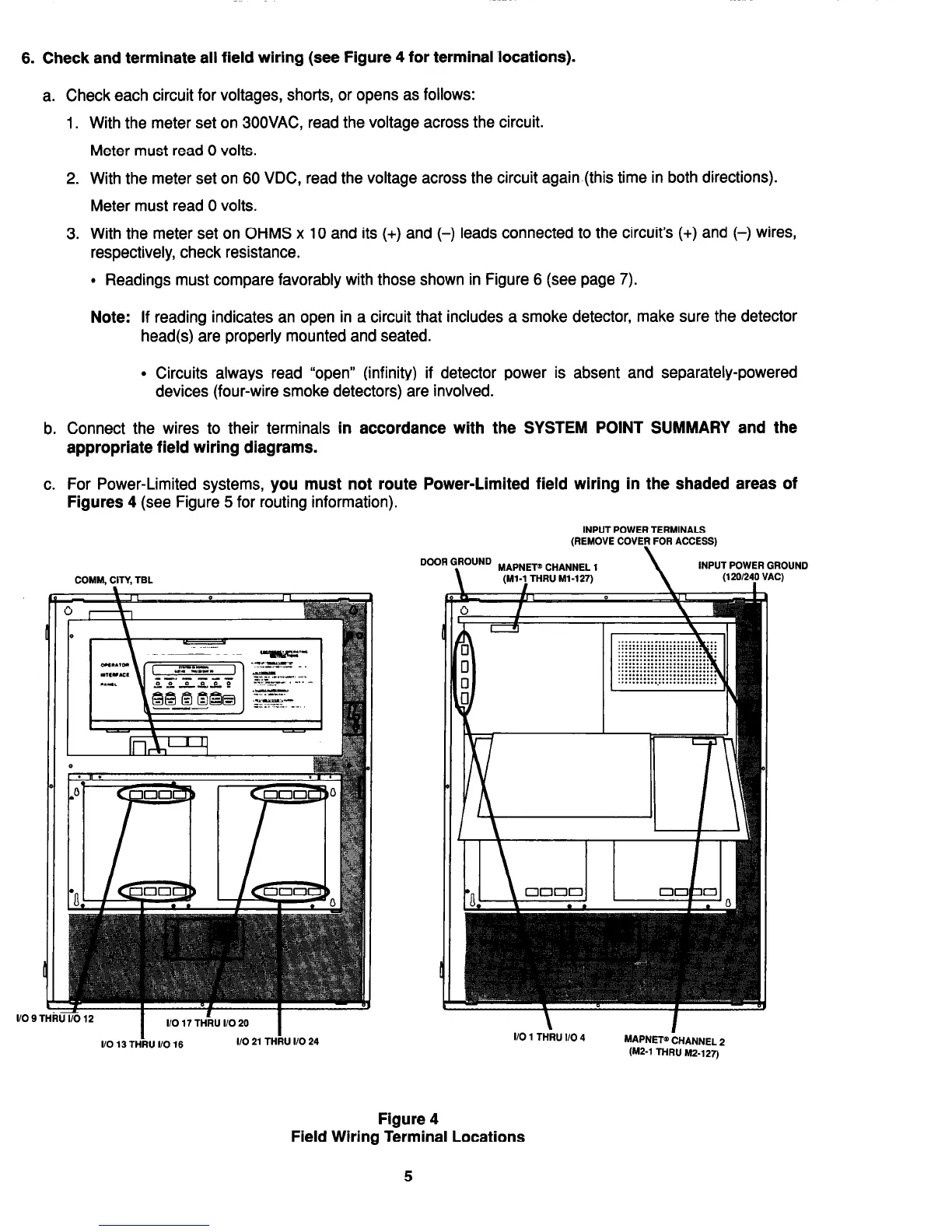
c. For Power-Limited systems,
you must not route Power-Limited field wiring in the shaded areas of
Figures
4 (see Figure 5 for routing information).
INPUT POWER TERMINALS
(REMOVE COVER FOR ACCESS)
DooR GRoUND MAPNET” CHANNEL 1
\ \
INPUT POWER GROUND
COMM, CITY, TEL
(Ml-1 THRU M-127)
(120124j VAC)
‘THRU l/O12
I
I/O 17 THhJ I/O 20
I
I/O 13 THRU I/O 16 I/O 21 THRU I/O 24
I/O 1 THRU I/O 4
MAPNET@ CHANNEL 2
W-1
THRU M2-127)
Figure 4
Field Wiring Terminal Locations
5
Technical Manuals Online! - http://www.tech-man.com