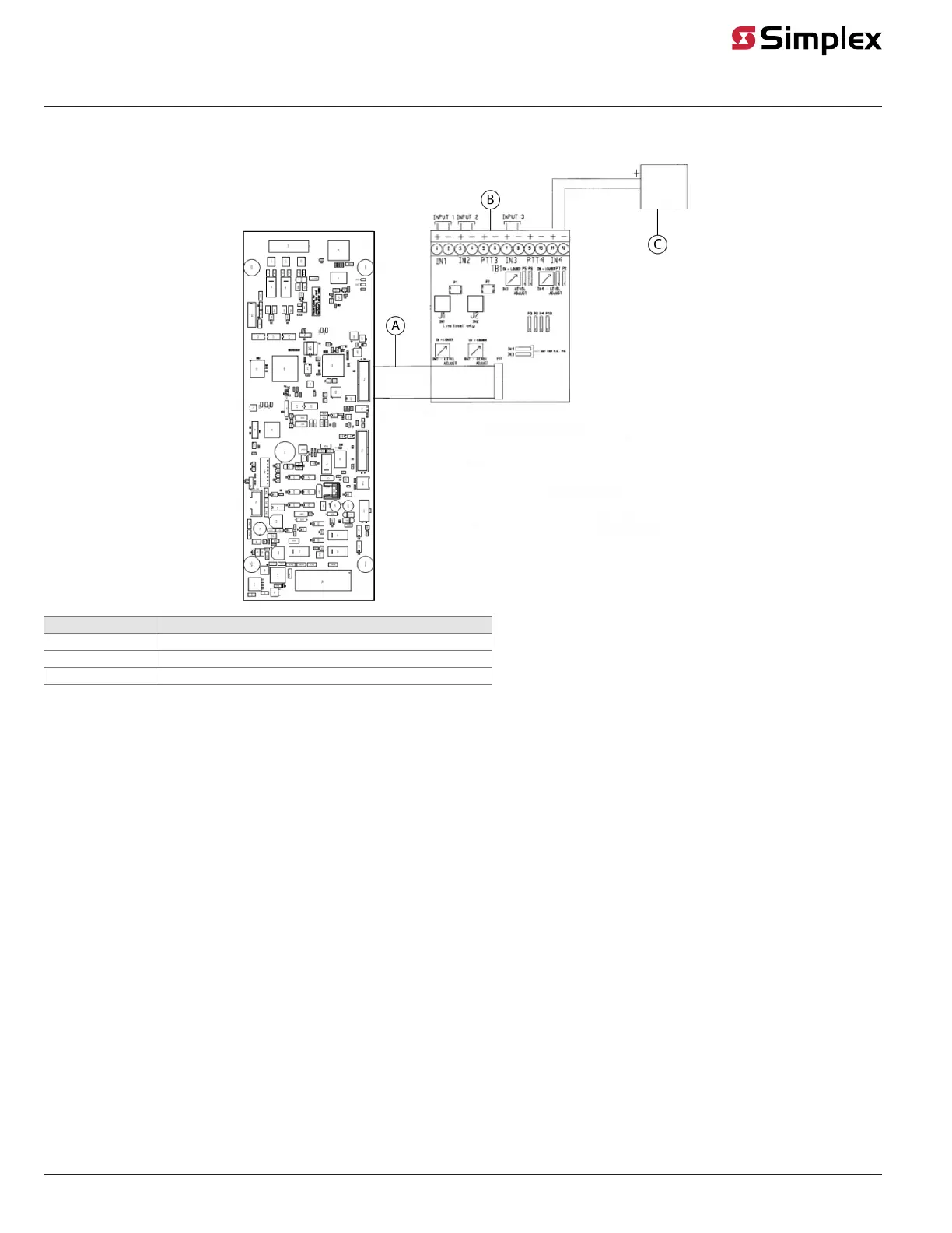
Audio Input Card/line level input interconnections
Figure 10: Line level input interconnections with Audio Input Option Card
Callout Description
A 734-048 Harness assy
B 637-063 Audio Input Option Card
C Typical audio source
Note: Use input trimpots to adjust input signals for desired volume.
Installation notes:
• Inputs set for line level are not supervised.
• All wiring is 18 AWG (0.8321 mm
2
) to 12 AWG (3.309 mm
2
).
• Audio wiring is not to be mixed in the same jacket with other wiring, including other audio wiring.
• Wire distance depends on the signal supplier. See the manufacturer documentation for requirements.
• All option card inputs support line level signals.
• Set audio input card jumpers for desired input sources as shown in Configuring the ES Net Audio Controller Card.
• All wiring that leaves the building requires the 2081-9044 Overvoltage Protector at each entry or exit to the building. A maximum of four
overvoltage protectors are allowed. Each 2081-9044 adds 6 Ohms and 0.006 μF.
• Inputs 1 and 2 are transformer-coupled inputs.
• J1 and J2 are the same as points IN1 and IN2, but accept RCA-style connectors (line level only).
• DC input impedance is greater than 900 Ohms.
• Line level is defined as 707 mV RMS, 600 Ohms output impedance.
• If you require a shield, connect the shield according to the signal supplier's instructions. Do not connect the shield to the FACU ground.
Note: Refer to Fire Alarm System Audio Input Card Installation Instructions 579-160 for information on the audio input card.
page 13 579-1408 Rev. B
ES Net Digital Audio Controller Installation Instructions