4100-1411 ES Net Digital Audio Controller with audio riser interconnections to TICs or the 4120 network
audio riser controller module (constant supervision applications)
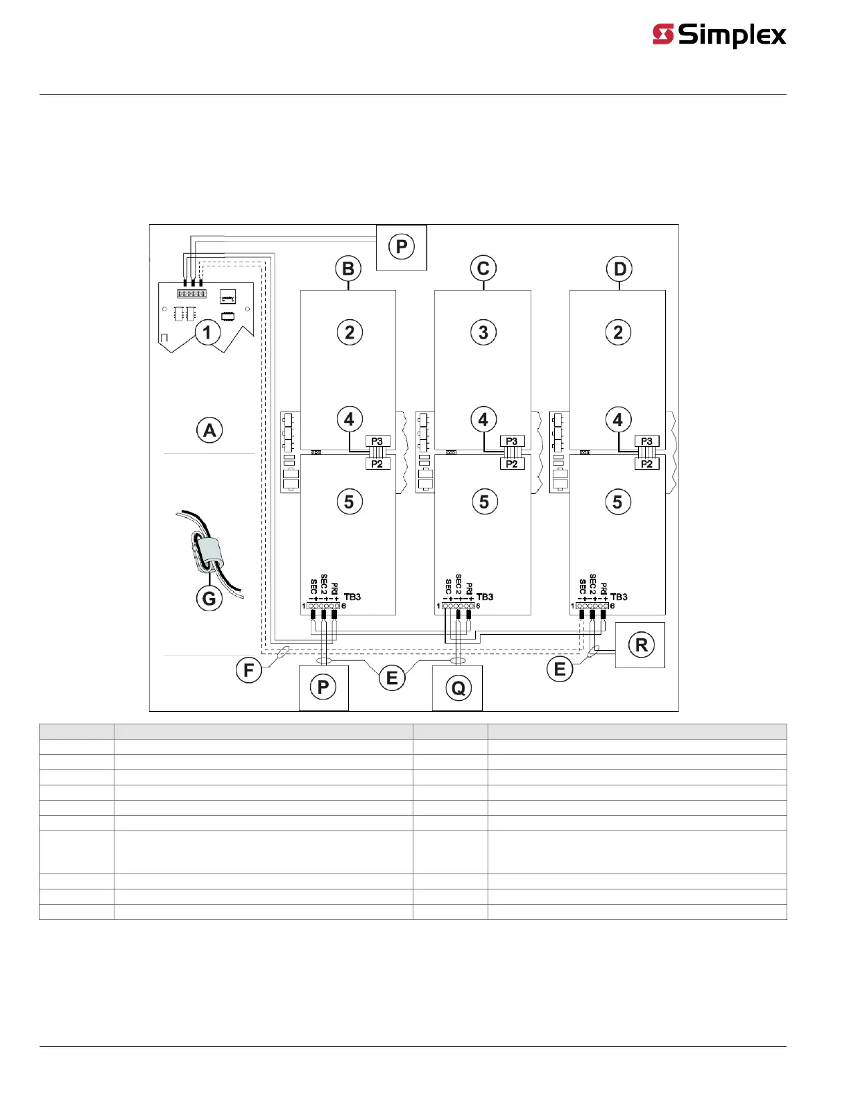
Note: To use the following audio riser interconnections with a ES Net DAC you must set the card in Digital Audio Controller mode.
Figure 14 is an illustration of class A and class B digital wiring from the 4100-1411 ES Net Digital Audio Controller to the digital audio risers connected
to TICs or the 4120 Network Audio Riser Controller Module.
Figure 14: Digital Audio Interconnections with 4100-1411 Digital Audio Controller
Callout Description Callout Description
1 4100-1411 ES Net Digital Audio Controller (0566-1291) A Node 1: Host panel
2 4100-0620 Basic TIC or 4100-0625 Local Mode TIC B Node 1: Miniplex transponder
3 4100-0623 Audio Riser Controller Module C Node 2: Control panel
4 Harness 733-997 D Node 2: Miniplex transponder
5 4100-0622 Digital Audio Riser (566-407, 566-1000) E DAR to primary input
— — F Dashed lines are for class A operation.
— — G Ferrite bead, required on primary and secondary DAR.
Loop wires once through the supplied ferrite beads as
shown.
— — P Node P, class B only
— — Q Node Q, class B only
— — R Node R, class B only
Installation notes:
• All wiring is 18 AWG (0.8321 mm
2
), unshielded twisted pair.
• Maximum wire distance: 2,500 ft (762 m) from digital audio controller primary to the primary of the first Digital Audio Riser Interface Card (DARIC).
• Maximum distance between subsequent nodes: 2,500 ft (762 m)
• Maximum line distance and capacitance between nodes: 18 AWG (0.8321 mm
2
): 40 Ohms maximum, 0.055 μF maximum
page 18 579-1408 Rev. B
ES Net Digital Audio Controller Installation Instructions