Audio Input Card/typical audio interconnections
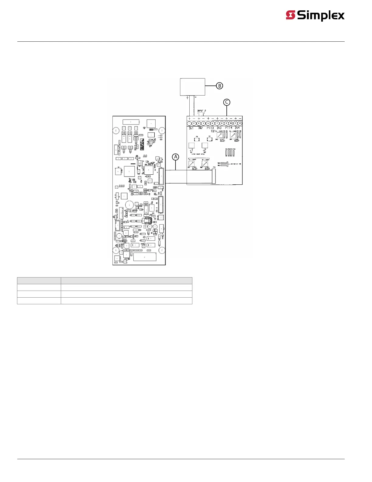
Figure 11 shows wiring for a 10 VRMS, 25 VRMS or 70.7 VRMS input through an audio input option card.
Figure 11: Audio Input Card with typical audio interconnections
Callout Description
A 734-048 Harness assy
B Typical audio source
C 637-063 Audio Input Option Card
Note: For the Audio Input Option Card, use input trimpots to adjust input signals for desired volume.
Installation notes:
• Inputs set for 25 VRMS or 70.7 VRMS audio level are not supervised.
• All wiring is 18 AWG (0.8321 mm
2
) to 12 AWG (3.309 mm
2
).
• Wire distance depends on the signal supplier. See the manufacturer documentation for requirements.
• Only inputs 1 and 2 support 25 VRMS/70.7 VRMS audio.
• Inputs 1 and 2 are transformer-coupled inputs.
• DC input impedance: 60 Kohms minimum (25 VRMS setting).
• DC input impedance: 170 Kohms minimum (70.7 VRMS setting).
• Set audio input card jumpers for desired input sources.
• If you require a shield, connect the shield per the signal supplier's instructions. Do not connect the shield to the FACU ground.
Note: Refer to Fire Alarm System Audio Input Card Installation Instructions 579-160 for information on the audio input card.
page 14 579-1408 Rev. B
ES Net Digital Audio Controller Installation Instructions