4005 Module Features
The CPU board contains the main microprocessor and
panel programming, evaluates the status of all I/O
modules, processes the required responses, and provides a
watchdog timer that resets the panel in the event of an
abnormal operation. Additional details are below.
• Controls the LCD readout and switches that comprise
the operator interface
• Controls the flash EPROM that contains the non-volatile
site-specific programming information
•
4-Wire Smoke Detector Power provides a 5 second
reset; rated 500 mA @ 24 VDC, open collector output,
and is power-limited and short circuit protected
•
Remote Unit Serial Interface (RUI) output provides
connections for up to 16, Class B supervised remote
annunciators, Remote Control Unit (RCU) model
4602-9102,or Status Command Unit (SCU) model
4602-9101; (see additional description under
Accessories on page 5)
Power Distribution Board Features:
• Provides connections for up to 5 plug-in module cards
•
Auxiliary power connections. Two power-limited
connections are provided, each rated for 2 A @ 24 VDC;
connections are isolated from NAC power
Power Supply/Battery Charger features:
• Switch Selectable for 120 or 240 VAC
•
24 VDC Power, regulated and power-limited, is
available specifically for notification appliances and
auxiliary output use via two taps of 2 A each; rated 4 A
for Special Application Appliances and 2 A for
Regulated 24 DC power
•
Internal System Operating Power is supplied via
separate power-limited connections.
•
Battery Charging for up to 18 Ah batteries mounted
within the 4005 cabinet and up to 33 Ah batteries when
mounted in an external battery cabinet.
•
Function Monitoring. Includes: missing, depleted, and
low battery, Earth fault detection, AC power loss, AC
power brownout (low input voltage), signal power
overload, supply voltage monitoring, and charger failure.
•
Depleted Battery Trouble Indication advises when
standby operation has exceeded battery capacity.
Internal DACT Module features:
• Reports Alarm, Supervisory, Trouble, and AC Failure
• Dual line operation with automatic 24 hour test and
programmable power fail report delay
Eight, Initiating Device Circuits (IDCs) features:
• Two, 4 circuit IDC plug-in modules are standard,
providing 8, Class B IDCs
• Standard IDCs are low current and support up to 20
Simplex detectors per IDC at 2 mA maximum (for
detectors with relay bases, use high current expansion
modules, see chart on page 7)
4005 Module Features (Continued)
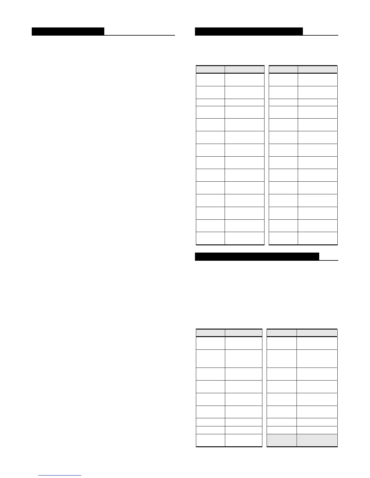
IDC operation is individually programmable with
the following 28 operating mode choices (the abbreviated
description is part of the IDC display information):
Point Type Description Point Type Description
FIRE
Fire Monitor
Zone
FPUMP
Fire Pump
Monitor
WATER
WaterFlow
Monitor
SFPUMP
Supervised Fire
Pump
HEAT Heat Detector S2STAGE 2 Stage Monitor
DUCT Duct Detector
SO
Sprinkler
Normally Open
FLAME Flame Detector
SC
Sprinkler
Normally Closed
PULL
Manual Pull
Station
WSO
Waterflow/
Sprinkler Open
SMOKE Smoke Detector
WSC
Waterflow/
Sprinkler Closed
EMERG
Monitor-Fire
Emergency
SUPV
Supervisory
Monitor
SFIRE
Monitor-
Smoke/Fire
UTIL Utility Monitor
VFIRE
Monitor-Verified
Smoke/Pull
TROUBLE Trouble Monitor
SPULL
Monitor-
Smoke/Pull
VSMOKE
Verified Smoke
Detector
VSPULL
Verified
Smoke/Pull
GVMON
Generic Verified
Zone
GENMON
Generator
Monitor
LATSUPV
Supervisory
Latching
SGENMON
Supervisory
Generator
STYLEC
Monitor-Style C
Monitor
Notification Appliance Circuits (NACs)
One, 4 circuit NAC/Relay plug-in module is standard,
providing 4, Class B NACs that can be individually
reconfigured for dry contact relay operation.
NAC operation is individually programmable
as
Steady Signaling, Temporal Pattern, March Time @
20 BPM, or March Time @ 120 BPM, and with the
following 17 operating modes (the abbreviated
description is part of the NAC display information):
Point Type Description Point Type Description
SSIGNAL
Fire Signal (On
until Silence)
RWATER
WaterFlow (On
until Reset)
RSIGNAL
Fire Signal (On
until Reset)
SUPV
Sprinkler
Supervisory
Signal
TSIGNAL
Trouble (On
until Clear)
PRIMARY
Elevator Capture
(primary
BSIGNAL
Trouble (On
until ACK)
ALTERN
Elevator Capture
(alternate)
SVISUAL
Visual (On until
Silence)
AHUR AHU Relay
RVISUAL
Visual (On until
Reset)
AHUO AHU On Relay
CODED Coded Signal
AHUF AHU Off Relay
SIGNAL Signal Circuit
DHOLDER Door Holder
SWATER
WaterFlow (On
until Silence)
2 S4005-0001-9 3/2009

 Loading...


