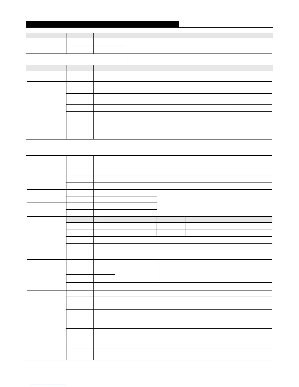
Category Model Description
4005-9101* Beige cabinet
Panel with
Cabinet
4005-9102 Red cabinet
4005 Fire Alarm Control Panel; includes 8 standard IDCs, 4 NAC/Relay
circuits, 4 A power supply/battery charger, cabinet and door, and internal Dual
Line DACT with two RJ45 plug DACT Cables, 14 ft long (4.3 m)
* 4005-9101C is the ULC English version; 4005-9101CF is the ULC French version; both 4005-9101C and 4005-9101CF models delete the
Dual Line DACT and include low battery cutout operation.
Category Model Description
Electronics Only 4005-9150
4005 Fire Alarm Control Panel, 8 high current IDCs, 4 NAC/Relay Circuits, 4 A power supply,
internal Dual Line DACT; requires 4002 Adapter Kit or separately ordered cabinet and door
4005-9806
Four Circuit Class A Adapter Module for IDC and/or NAC modules, standard or expansion;
mounts on top of plug-in IDC/NAC module; circuits convert either NAC or IDC, or combination
4005-9807
Additional Five Slot Power Distribution Module, required when plug-in
module count exceeds five, or for connection of Expansion Power Supply
Qty, 1 Max.
4005-9809** Single (1) Circuit City Module, chassis mounted, below CPU Qty, 2 Max.**
4005-9810**
Internal Dual Line DACT; aftermarket add-on; for connecting to RJ31X Telco
jacks, includes two DACT Cables with RJ45 Plug, 14 ft long (4.3 m)
Qty, 1 Max.**
Optional Modules
4005-9813
Expansion Power Supply, 24 VDC, 5 A, regulated; chassis mounted beneath
left side modules; requires 4005-9807 Power Distribution Module and
provides power to 4005-9807 only
Qty, 1 Max.
** DACT module is standard equipment on 4005-9101 and 4005-9102. Operation allows for either a DACT module or one or two City
Connection modules. The DACT is programmed using a terminal or a laptop computer in terminal emulation mode. Connection and
programming details are provided with Installation Instructions 574-049.
4005-9803 Standard Operation, 2 Circuit IDC with 2 NAC/Relay circuits
4005-9804 Standard Operation, 4 Circuit IDC Module
4005-9805 4 Circuit NAC/Relay Module
4005-9808 8 Circuit Programmable I/O Module
Expansion
Modules
(capacity is 10
expansion slots, 3
expansion slots are
used in base panel)
4005-9824 4 Circuit IDC Module, high current operation, Class B, for detectors with relay bases
2975-9209 Beige 4005 Cabinet
Cabinets
2975-9210 Red 4005 Cabinet
4005-9857 Beige Door
Doors
4005-9858 Red Door
Order cabinets if required for pre-installation. 4005-9150
Electronics only model requires a cabinet and door or a 4002
Adapter Kit.
Model Description Model Description
2081-9272 6.2 Ah Battery, 12 VDC 2081-9288 12.7 Ah Battery, 12 VDC
2081-9274 10 Ah Battery, 12 VDC 2081-9275 18 Ah Battery, 12 VDC
2081-9271 33 Ah Battery, 12 VDC; requires External Battery Cabinet 4009-9802
Batteries
select one model
number;
two
required for
24 VDC system
power;
see page 7
for currents
4009-9802
External Battery Cabinet, beige with solid door; includes battery harness; mounts close-nippled
to 4005 cabinet; for up to 33 Ah batteries; cabinet size:
25-3/4” W x 20-3/4” H x 4-1/8” D (654 mm x 527 mm x 105 mm)
4005-9850
Two Unit
4005-9851
Four Unit
4005-9852
Six Unit
4002 Cabinet size
Includes 4005 chassis adapter plate with beige retainer
panel
4002 Adapter Kits
(for mounting
4005-9150
electronics into a
Simplex Model 4002
cabinet)
4005-9854
Four Unit 4002 Cabinet size, includes 4005 chassis adapter plate with red retainer panel
4081-9004 6.8 kΩ, 1/2W, End-of-Line Resistor Harness for standard IDCs; (ref. 733-886)
4081-9002 3.3 kΩ, 1 W, End-of-Line Resistor Harness for high current IDCs; (ref. 733-893)
4081-9008 10 kΩ, 1/2 W, End-of-Line Resistor Harness for NACs; (ref. 733-894)
4081-9001 2.2 kΩ, 1/2 W, End-of-Line Resistor Harness for 8 Pt I/O input mode; (ref. 733-892)
4081-9007 1.2 kΩ, 1 W, End-of-Line Resistor Harness for N.O. tamper switch monitoring; (ref. 733-891)
4602-9101 Status Command Unit (SCU), 16 LED serial connection annunciator
4602-9102
Remote Command Unit (RCU), 8 LED serial connection annunciator with remote tone-alert and
control panel status LEDs, and switch control for Trouble and Alarm Silence, System Reset,
and Manual Evacuation (4602 Series Annunciators are available for multiple packaging
applications, for further information, refer to data sheets S4602-0001 and S4602-0004)
4005 Accessory
Selection
Reference
4601 Series
LED/Switch Annunciators, modular design allows selection of required LEDs and control
switches (refer to data sheet S4601-0002)
6 S4005-0001-9 3/2009
4005 Product Selection (refer to page 7 for specifications details)
 Loading...


