NAC Relay Mode Operation
NAC/Relay Selection. Each NAC can be on-site
selected for NAC operation or for unsupervised, dry
contact, auxiliary relay operation. When operating in the
relay mode, either the normally open or the normally
closed contact can be connected to the output terminal
block. Contacts are rated at 2 A @ 32 VDC, for transient
suppressed loads.
Relay Operation is individually programmable with the
following 17 operating mode choices (the abbreviated
description is part of the relay display information).
Relay Modes:
Point Type Description Point Type Description
RELAY Auxiliary Relay
BRELAY
Trouble Relay
(On until Ack)
PRIMARY
Elevator Capture
(Primary)
DHOLDER Door Holder
ALTERN
Elevator Capture
(Alternate)
SVISUAL
Visual (On until
Silence)
AHUR AHU Relay
RVISUAL
Visual (On until
Reset)
AHUO AHU On Relay CODED Coded Relay
AHUF AHU Off Relay
SWATER
Waterflow Relay
(On until
Silence)
SRELAY
Fire Relay (On
until Silence)
RWATER
Waterflow Relay
(On until Reset)
RRELAY
Fire Relay (On
until Ack)
SUPV
Supervisory
Relay
TRELAY
Trouble Relay (On
until Clear)
4005 Basic Operator Functions
Display Indications. Upon receiving an abnormal
condition of alarm, supervisory, or trouble, the 80
character backlit LCD will identify the quantity and type
of abnormal indications. With the locked door closed, the
display, status LEDs and primary operator switches are
visible through the transparent door viewing panel as
shown in Figure 1 below. This figure represents the LCD
during normal conditions showing normal status, time,
and date.
ALARM
ACK
SUPV
ACK
TROUBLE
ACK
ALARM
SILENCE
SYSTEM
RESET
FIRE
ALARM
SYSTEM
SUPERVISORY
SYSTEM
TROUBLE
ALARM
SILENCED
AC
POWER
Figure 1. Basic Operator Function Keys with Normal
Display of Status, Time, and Date
4005 Basic Operator Functions (Continued)
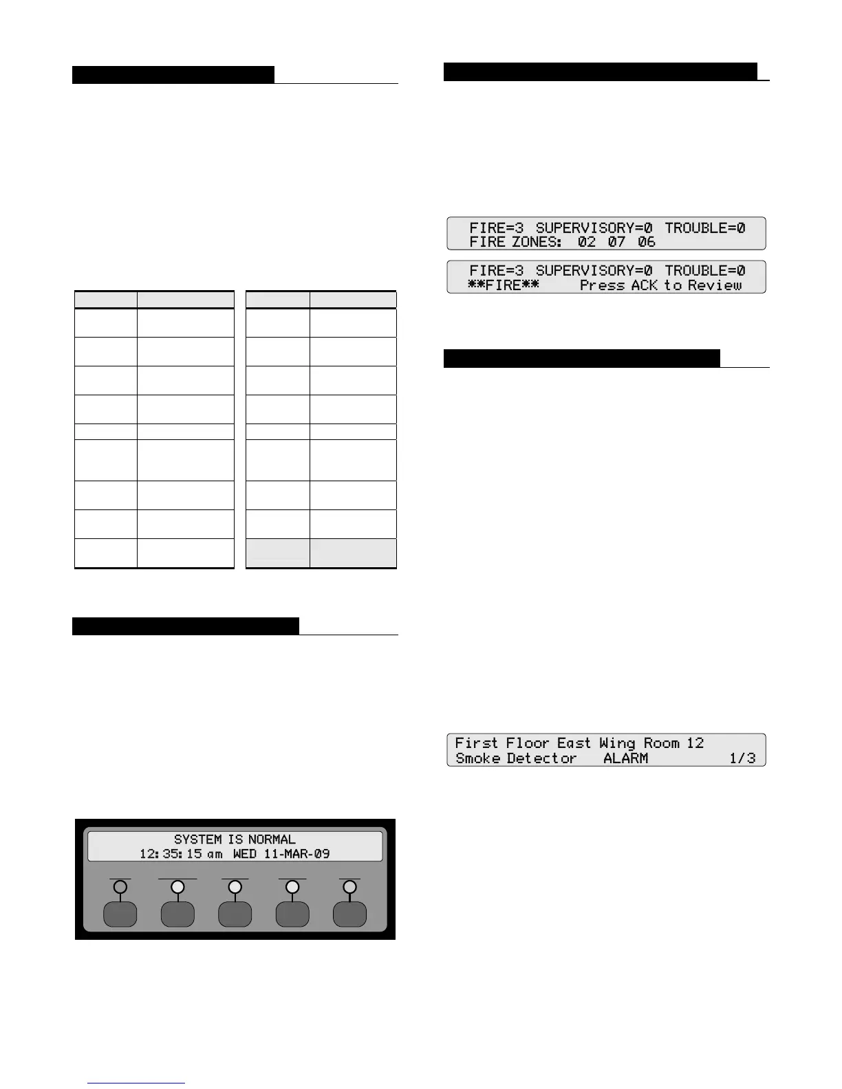
Typical Displays. Figure 2 (below) represents typical
fire alarm display screens. For this example, the presence
of three fire alarm conditions is shown in the top screen –
fire zones 2, 7, and 6, displayed in chronological order of
occurrence (up to 10 zones may be shown). The display
will alternate with the one shown below it as the operator
is prompted to assist with the next required action.
Figure 2. Typical 4005 Displays with Alarm Activity
Alarm, Supervisory, and Trouble ACK
Operator Actions. The ALARM ACK, SUPV ACK, or
TROUBLE ACK key will silence the local tone-alert,
corresponding to the type of abnormal condition.
Subsequent entry of the appropriate ACK key will
chronologically scroll through the specifics for each
abnormal condition. Screen information includes custom
labels for each zone that provides a detailed report of the
location, device type description, device condition, and
list count for the first point in the Alarm, Supervisory, or
Trouble list.
Custom Label Display. Figure 3 represents a typical
screen that would appear after using the ALARM ACK
key to scroll to the first fire condition. It displays the zone
location as “First Floor East Wing Room 12”, the device
type as “Smoke Detector” and the device condition of
“Alarm”. The 1/3 indicates that the displayed alarm is the
first of three alarms present in the panel at this time.
Site-specific labels can be upper or lower case and can
provide discrete annunciation that can assist fire response
with clearly defined zone locations and device types.
Figure 3. Typical 4005 Fire Alarm Information Custom
Label Display
Alarm Silence. The ALARM SILENCE key will
silence the notification appliances programmed for
on-until-silence (typically audible notification appliances)
and the ALARM SILENCED LED will remain
illuminated until the panel is reset.
System Reset. When the source of the abnormal
condition is corrected, the SYSTEM RESET key will
reset the panel and return the status to normal.
3 S4005-0001-9 3/2009

 Loading...


