9 - 15
Shift Linkage Service
Refer to Figure 13.
SHIFT LEVER REMOVAL & INSTALLATION
1. Remove the shift lever knob (A, Figure 13).
2. Disconnect the shift lever spring (C) from the shift
lever (B).
3. Remove the cotter pins (D) and remove the shift lever
from the pivot shaft (E).
Install in reverse order of removal.
PIVOT SHAFT REMOVAL & INSTALLATION
The pivot shaft (E) is part of the rear frame wrapper and
is not serviced separately. See Section 13, SEAT &
SEAT DECK SERVICE, for additional information.
SHIFT LINK REMOVAL & INSTALLATION
To remove the shift links (O and V) remove the the car-
riage bolts and locknuts connecting the links.
BELL CRANK ASSEMBLY REMOVAL & INSTALLATION
1. Park the tractor on a flat level surface, such as a con-
crete floor, and block the wheels. Do not engage the
parking brake.
2. Disconnect the upper shift link (V, Figure 13) from the
bell crank (L) by removing the nut (U) and carriage
bolt (K).
3. Disconnect the the lower shift link (O, Figure 13) from
the bell crank (L) by removing the nut (M) and and
carriage bolt (T).
4. Disconnect the rear brake rod (K, Figure 11) from the
transmission.
5. Engage the parking brake to slacken the drive belt.
6. Remove the taptite screws (G, Figure 14) from the
torque straps (H) and transmission casing.
7. Loosen the capscrews (D and E, Figure 14 ) securing
the torsion bar anchors (C).
8. Loosen transmission mounting capscrews (F, Figure
14). This should allow adequate clearance to access
the bell crank capscrew (G, Figure 13).
9. Remove the bell crank capscrew (G) and related
hardware from the carrier pivot shaft. Remove the
bell crank (L, Figure 13).
Reinstall in reverse order of removal. Be sure to lubri-
cate the carrier pivot shaft and bushings (J, Figure 13)
with lithium grease. After installation, perform BRAKE &
BRAKE SPRING ADJUSTMENT and NEUTRAL
ADJUSTMENT procedures in Section 4.
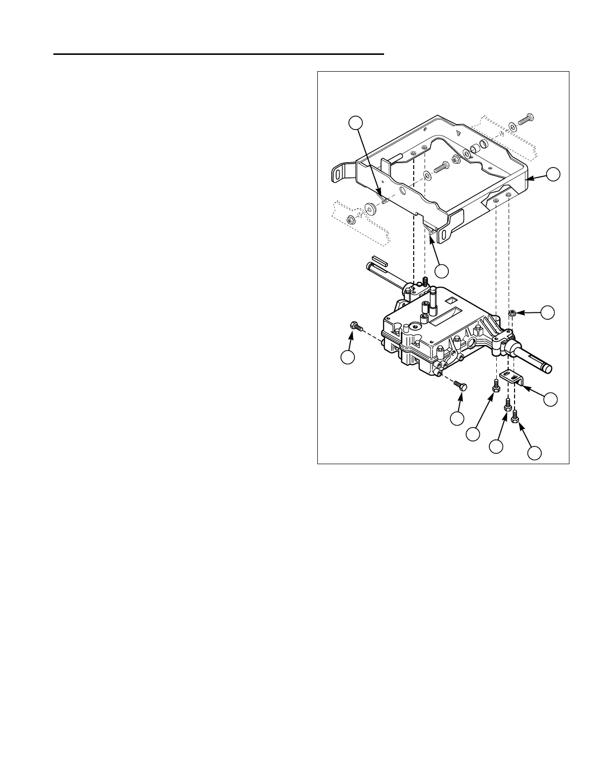
Figure 14. Transmission & Carrier Assembly
A. Transmission Carrier E. Capscrew
B. Flange Locknut F. Capscrew
C. Anchor G. Taptite Screws
D. Capscrew H. Torque Strap
9 Drive Controls Service
Peerless (Gear Drive) Models
A
B
C
D
F
E
G
H
H
G
 Loading...