7 Electrical System Service
Linear Circuit Diagrams
7 - 12
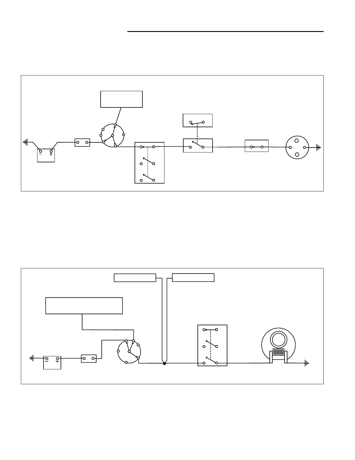
LINEAR CIRCUIT DIAGRAMS
The following three diagrams show the flow of current
with the key switch in its three positions.
N.O.
N.O.
N.C .
Start Position
Run Position
Start Position
When the key is turned to the START position current
travels through the circuit breaker to the key switch, and
from there on to the safety switches.
When the PTO switch is turned off, the clutch / brake
pedal is depressed, and the ground speed control lever
is placed in neutral (Peerless models only) the solenoid
receives power.
The solenoid is essentially a large electrically powered
switch. When the small posts of the solenoid receive
power, the internal power switch closes sending power to
the starter motor.
If one of the safety switches is open, the solenoid will not
send power to the starter.
Run Position
When the key is turned to the RUN position (after the
engine has started) the battery, alternator, fuel solenoid,
head lights, and PTO clutch are connected through the
key switch.
This multiple splice supplies alternator power to the bat-
tery for charging and to the rest of the tractor electrical
system to run the accessories and PTO clutch.
 Loading...