4 - 7
4 Adjustments
Ground Speed Control Foot Pedal Adjustment
GROUND SPEED CONTROL
FOOT PEDAL ADJUSTMENT
Tuff Torq K-56 Models
If the unit does not reach top speed with the forward
direction pedal fully depressed, perform the following
adjustment with the engine off and PTO disengaged.
1. Park the tractor on a level surface such as a concrete
floor.
2. Loosen the nut (A, Figure 12) securing the control rod
(B) to the hydro control lever.
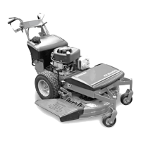
3. Place a 2-1/4” thick wood block between the bottom
of the foot pedal and the footrest (see Figure 11).
Hold the pedal against the wood block and tighten
the nut (See A, Figure 12).
NOTE: If a wood block is not available, measure the dis-
tance between the bottom of the pedal and the plastic
plug in the footrest. The distance should be 2-1/4” as
shown in Figure 11.
Figure 11. Forward Speed Adjustment - Hydro
A
B
2-1/4”
Unit pictured from above with frame removed.
Figure 12. Hydro Foot Pedal Adjustment
A. Nut B. Control Rod
Hydro-Gear 0500 / 0650 Models
Note: Perform Neutral Adjustment procedure before
adjusting the Forward Speed.
If the unit does not reach top speed with the forward
direction pedal fully depressed, perform the following
adjustment with the engine off and PTO disengaged.
1. See Figure 12. Loosen the nut (A) securing the con-
trol rod to the hydro control lever.
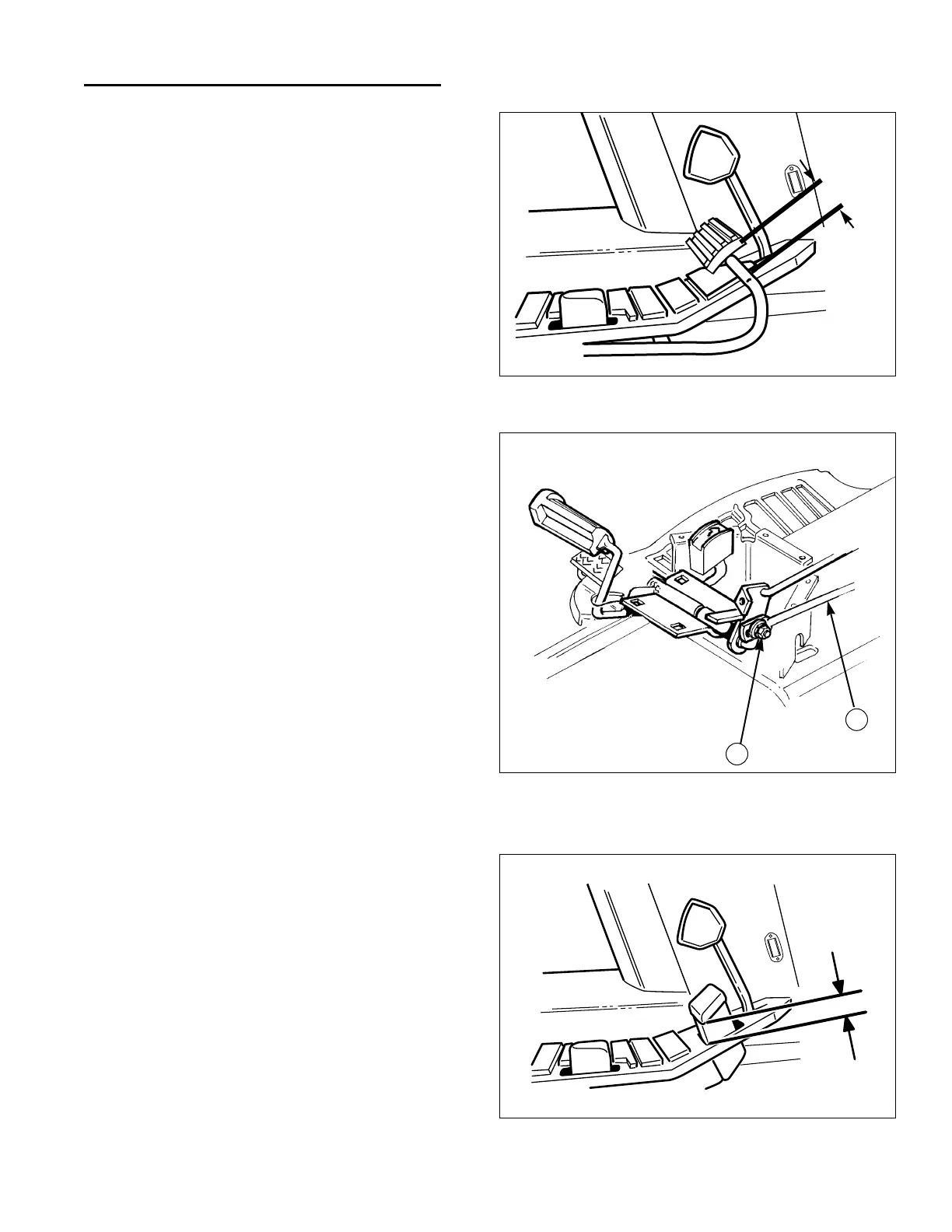
2. Position the pedal so the distance between the frame
and bottom edge of the pedal is 1-3/4" as shown in
Figure 13.
3. With pedal in this position, tighten the nut (A, Figure
12).
4. The stop pin (See item D, Figures 8 and 9 under the
NEUTRAL ADJUSTMENT) should be positioned near
the end of the cam slot as shown when the front
pedal edge is 1/4" above the frame (pedal fully
depressed). If it is not, loosen nut (A, Figure 12) and
adjust pedal as necessary, then retighten nut.
NOTE: The stop pin (See item D, Figures 8 and 9 under
the NEUTRAL ADJUSTMENT) should be positioned near
the end of the cam slot when the front pedal edge is 1/4"
above the frame (pedal fully depressed). The stop pin
should not “bottom out” in the cam slot. Increasing the
distance between the end of the cam slot and the stop
pin will increase reverse speed and decrease forward
speed.
Figure 13. Forward Speed Adjustment - Hydro
1-3/4”
 Loading...